LAUNCH Tyre Changer(TWC Series)
3
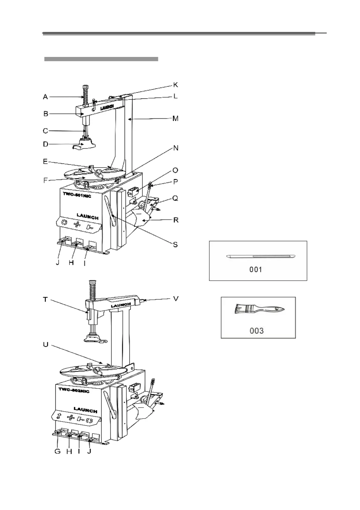
Main Structure
Fig.01-1
Fig.01-2
The main structure is shown in Fig. 01.
A. Return spring
B. Swing arm
C. Hexagonal column
D. Mount/demount head
E. Clamping jaw
F. Turntable
G. Tilting post control pedal
H. Clamping cylinder control pedal
I. Bead breaker control pedal
J. Turntable control pedal
K. Knob
L. Locking lever
M. Post
N. Clamping cylinder
O. Lubricant box
P. Bead breaker handle
Q. Bead breaker arm
R. Bead breaker shoe
S. Tyre lever
T. Locking handle
U. Air pressure regulator, gauge and lubricator assembly
V. Horizontal arm.
Accessories provided are shown in Fig.02
001-Tyre lever
002-Brush
Fig.02-a
Fig.02-b