31
5.4 STRUCTURE AND FUNCTIONS
5.5 MACHINE
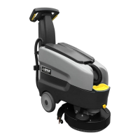
PHOTO A
1
*
Steering wheel (handlebar)
2
*
Control handle (deadman’s handle)
3
*
Suction hose
4
*
Suction hood and access to the
recovery tank
5
*
Recovery tank
6*
Solution tank
7
*
Recovery water tank drain hose plug
8
*
Recovery water tank drain hose
9
*
Solution water tank filling plug
10
*
Direction adjustment knob
11
*
Bumper wheel
12
*
Splash guard
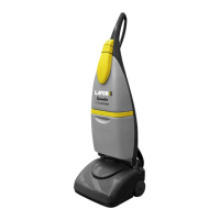
PHOTO B
13
*
Control panel
14
*
Electronic board cover
15
*
On- board battery charger
16
B
Battery charger plug
16
*
Power cable (only model AC 230V)
17
*
Socket of Battery security connector (An-
derson)
18
*
Battery security connector (Anderson)
19
*
Squeegee lifting/lowering lever
20*
Rear wheel
21
*
Grip adjustment and fastening knobs
PHOTO C
22
*
Detergent solution outlet flow adjustment
tap
23
*
Drain plug of filter and Solution water tank
(20* Rear wheel)
PHOTO D
24
*
Fixing bolts
25
*
Metal retainer for front rubber blade
26
*
Front rubber blade
27
*
Suction hose coupling pipe
28
*
Squeegee fixing pin
29
*
Rear rubber blade
30
*
Metal retainer for rubber blades
31
*
Metal retainer for rubber blades
PHOTO E
(13*) Control panel
32* ON/OFF Main switch:
Warning light on = switch ON
Warning light off = switch OFF
33* Brush motor switch:
Warning light on = In operation
Warning light off = Not in operation
34* Suction motor switch:
Warning light on = In operation
Warning light off = Not in operation
35* Automatic brush release:
Warning light on = In operation
Warning light off = Not in operation
36* Battery power test
37* Green led - full battery charge
38* Yellow led - 50% battery charge
39* Red led - battery discharged
PHOTO F
40* Suction filter
41* Battery compartment with 2 x 12V batteries
42* Battery connection diagram
43* Safety float
PHOTO G
44* Squeegee support
(28*) Squeegee fixing pin
PHOTO H
45* Squeegee fixing knob
(27*) Suction hose coupling pipe
44* Squeegee support
PHOTO I
45* Squeegee fixing knob
(27*) Suction hose coupling pipe
44* Squeegee support
PHOTO L
44* Squeegee support
PHOTO M
(24*) Fixing bolts
(29*) Rear rubber blade
(30*) Metal retainer for rubber blades
(31*) Squeegee fixing knob
 Loading...