Figure 4
Model 22242
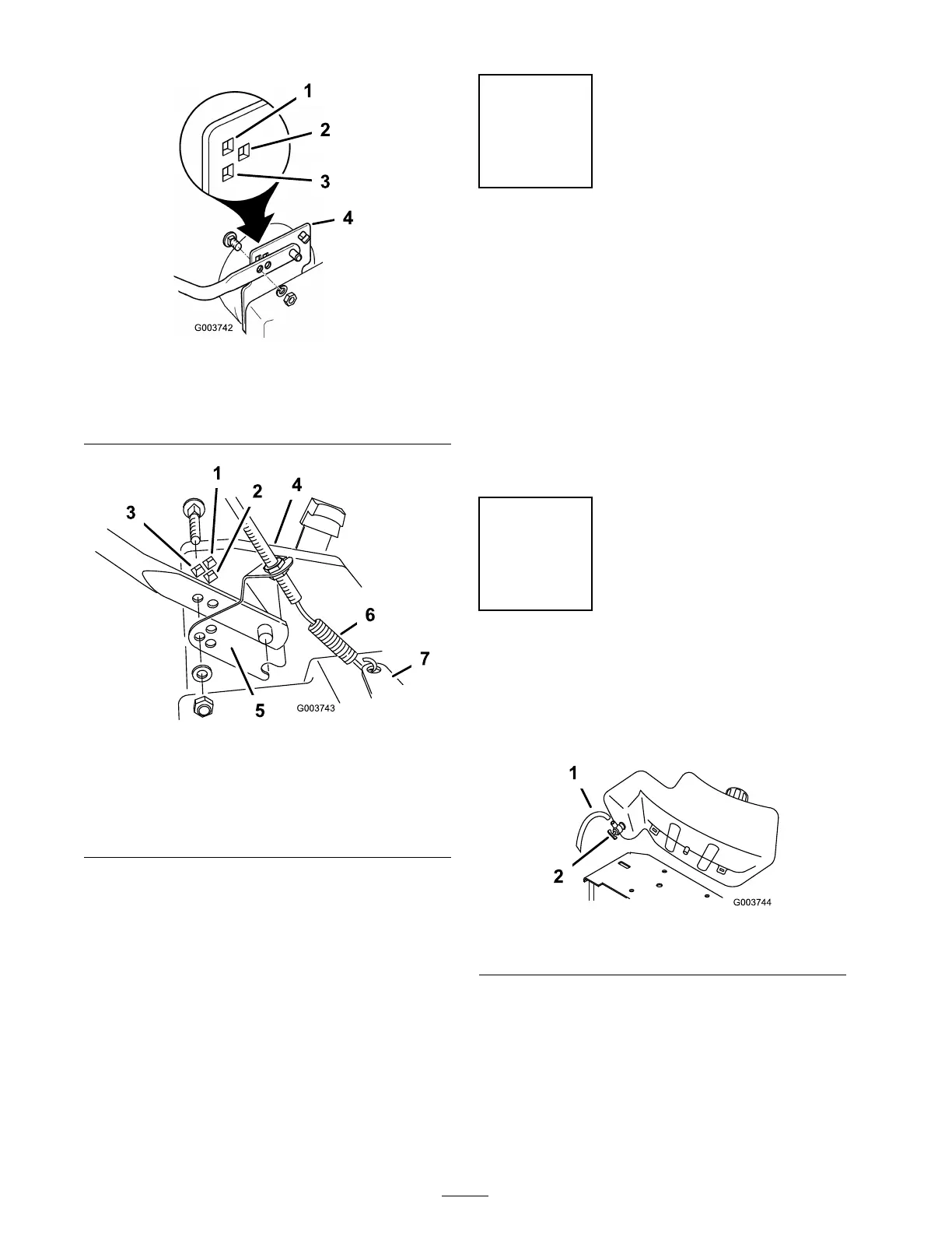
1. High setting
3. Low setting
2. Medium setting 4. Mower housing
Figure 5
Model 22243
1. High setting 5. Traction cable bracket
2. Medium setting 6. Traction cable spring
3. Low setting
7. Actuator bracket
4. Mower housing
4. Hook the traction cable spring into the actuator
brac k et ( Figure 4 ) (model 22242 only).
5. Matc h the three holes in the traction cable
brac k et to the three holes in the left side of hte
mo w er housing ( Figure 4 ) (model 22243 only).
Step
2
Adjusting the Fuel Tank
No Parts Required
Procedure
Y ou can set the handle height in 3 positions: high,
medium, and lo w ( Figure 4 or Figure 5 ). Select a
handle height position that is most comfor table
for y ou.
Align the holes in the lo w er handle section with the
holes in the mo w er housing . using the hardw are
sho wn in Figure 4 or Figure 5 , secure the handle
to the mo w er housing .
Step
3
Installing the Fuel Tank
No Parts Required
Procedure
1. Locate the fuel hose ( Figure 6 ).
Figure 6
1. Fuel hose 2. Fuel shutoff valve
Note: R emo v e and discard the cap on the
free end of the hose .
2. R emo v e and discard the red plastic cap from
the fuel shutoff v alv e ( Figure 6 ).
3. Push the hose onto the fuel shutoff v alv e in
the fuel tank, completely co v ering all the ridg es
of the fitting ( Figure 6 ).
8
 Loading...