7
3.
Secure the back of the chute and the handle to the
center hole in the chute ring with a carriage bolt, a
washer
, and a locknut. Position the washer and the
locknut on the outside of the chute (Fig. 3).
Note:
Rotate the chute ring to make the dischar
ge
chute assembly easier
.
4.
Secure the chute and the handle to the chute ring with
the remaining carriage bolts, washers, and locknuts.
T
ighten all locknuts securely
.
Installing
the Handle
1. Remove
the tie that secures the control cable to the
lower handle (Fig. 4).
2
1
3
905
Figure 4
1. Handle
2. Machine screw
3.
Eyebolt and spacer
2. Slide
the handle ends through the openings in the
shroud and onto the lower handles inside the shroud.
3.
Secure the right side of the handle with two machine
screws.
4.
Secure the left side of the handle with a machine
screw
, an eyebolt, and a spacer as shown in Figure 4.
Note:
Insert the eyebolt through the spacer before using it
to secure the handle to the snowthrower frame.
5.
Position the eyebolt perpendicular to the upper hole in
the left handle and tighten.
Installing
the Control Cable
1. Route
the control cable through the eyebolt on the left
side of the snowthrower (Fig. 4).
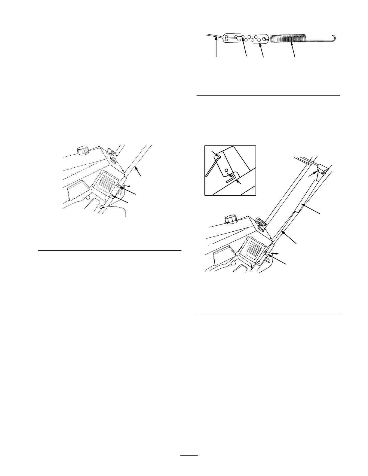
2.
Hook the spring into the round hole at end of the cable
adjuster (Fig. 5).
3.
Route the cable through the elongated hole in the cable
adjuster
. Insert the Z fitting on the end of the cable
into the third hole from the cable end of the cable
adjuster (Fig. 5).
897
4
3
21
Figure 5
1. Spring
2. Cable
adjuster
3.
Z fitting
4. Cable
4. Slide
the spring cover over the spring and the cable
adjuster
. Push the spring end through the hole at the
end of the spring cover
.
5.
Hook the spring into the top hole of the control bar
bracket (Fig. 6).
723
1/16-1/8
”
1
Figure 6
1. Eyebolt
and spacer
2.
Control cable
3.
Spring cover
4.
Control bar bracket
5. T
op hole
6. Move
control bar back toward the handle until there is
no slack in the cable. The gap between the control bar
bracket and the handle should be approximately 1/16
to 1/8 in. (0.16 to 0.32 cm). See inset in Figure 6. T
o
adjust this gap, refer to
Adjusting the Contr
ol Cable
on
page 1
1.
Note:
The control cable must always contain slack
when it is in the disengaged position.