32
THROTTLE AND STARTER SYSTEM
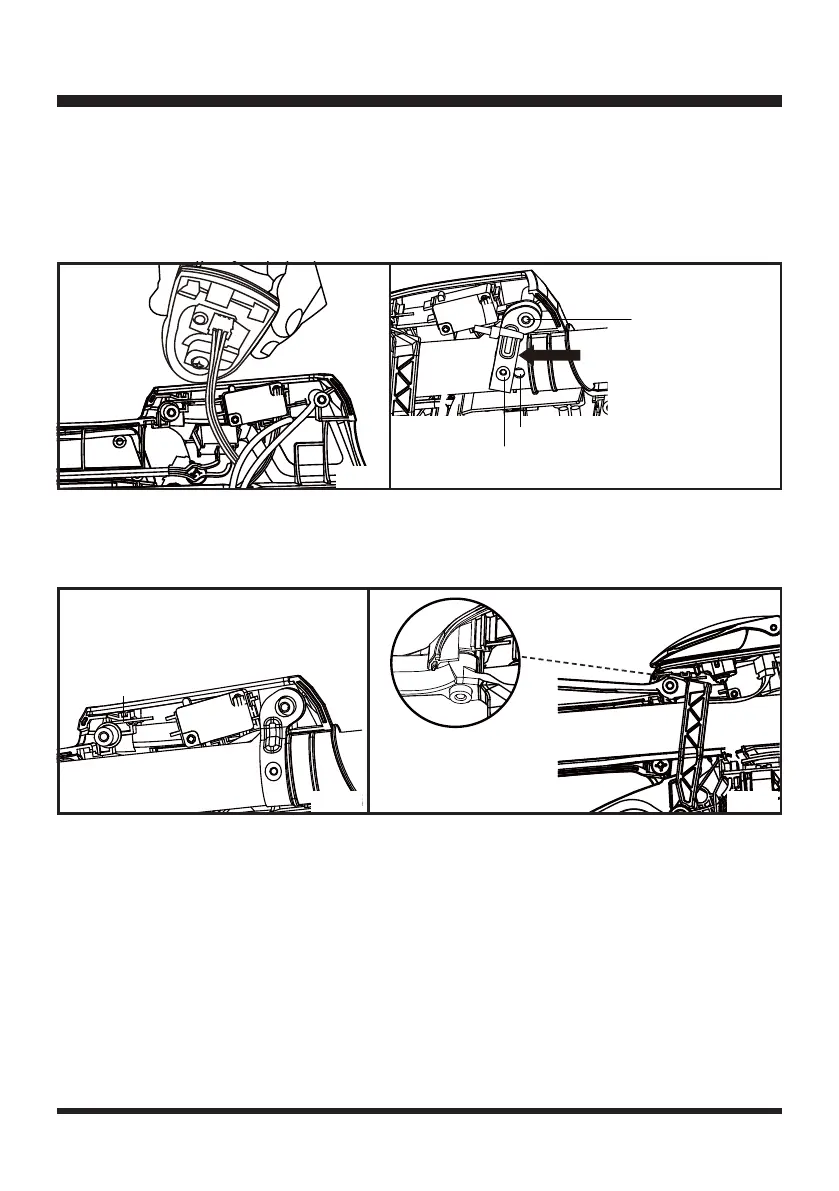
Ŷ&RQQHFWWKH/('OLJKWFDEOHWRWKHHOHFWULFVWDUWHUFRYHUSODWH$OZD\VSXOOJHQWO\DIWHUDVVHPEO\WR
ensure that terminals of the LED cable are connected in place (Fig. 59).
Ŷ,QVWDOOWKHVKDIW0DNHVXUHWKHSRVLWLRQKROHRQWKHUHWDLQHULVDWWDFKHGWRWKHVFUHZFROXPQ$GMXVW
the shaft in the direction of the arrow to place the protrusion on the retainer into the position hole on
the shaft. Fasten the retainer with a new cable tie (Fig. 60).
Ŷ7RLQVWDOOWKHWKURWWOHVDIHW\¿UVWSD\DWWHQWLRQWRWKHFRUUHFWGLUHFWLRQRIWKHWRUVLRQDOVSULQJZLWKWKH
long end upwards as shown (Fig. 61). Make sure the throttle safety and the torsional spring are
installed into place (Fig. 62). Install the electric starter cover plate.
Ŷ5HVWRUHWKHULJKWFRYHURIWKHPDLQKDQGOHE\WLJKWHQLQJWKHVFUHZV
Power Line Connection
Ŷ$OLJQDQGFRQQHFWWKHPDOHDQGIHPDOHWHUPLQDOVRIWKHZLULQJKDUQHVVRIWKHPDLQKDQGOHWRWKH
male and female terminals of the wiring harness of the engine. Always gently pull the wiring harness
once they are connected and make sure they are connected well without any loosening. Check that
all the insulation covering outside the wiring harness wrap the terminals completely. Ensure the
PHWDOWHUPLQDOVDUHQRWH[SRVHG)LJ
Fig. 60
Fig. 62
Fig. 59
Fig. 61
Position hole on
the retainer
Position hole on the shaft
Torsional Spring
Protrusion on the retainer

 Loading...