Do you have a question about the LCI HF3212-A75 and is the answer not in the manual?
Technical specifications for the 3-phase 200V-240V models.
Offers extensive monitoring, easy setup, comprehensive protection, programmable operations, and communication capabilities.
Explanation of harmonic currents and methods to suppress them using reactors and filters.
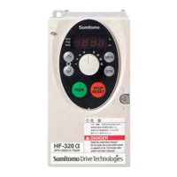
Detailed explanation of the front panel controls, indicators, and display functions.
Procedures for starting and stopping the motor using the operation panel keys.
Methods for setting the operating frequency via the built-in potentiometer and external signals.
Detailed technical specifications for 3-phase 200V class inverters.
Detailed technical specifications for 3-phase 400V class inverters.
Detailed technical specifications for 1-phase 200V class inverters.
Core control features including V/F control, torque boost, and acceleration/deceleration settings.
List of error codes, their corresponding problems, and potential causes for diagnosis.
Diagram illustrating wiring connections for sink logic configuration with common terminal as COM.
Diagram illustrating wiring connections for source logic configuration with common terminal as P24.
Mapping of function numbers to input and output terminals for custom configuration.
Important considerations for wiring, grounding, and selecting peripheral equipment for safe operation.
Guidelines for power supply connection, installation environment, and safe handling of the inverter.
Details on warranty period, conditions, exclusions, and seller responsibilities for the inverter.