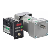
Main Circuit Terminals
Control Circuit Terminals
Modbus Port (RS-485)/ Keypad-601A
Type Symb
ol
Function Description
Terminal of Main
Circuit
Power
Source
L1,L2
AC power source input
terminals
For the single-phase power
source AC 200~240V.
Motor U,V,W
Drive outputs to motor
terminals
The terminals output three
phase variable frequency and
voltage to motor.
Grounding Grounding terminal
Grounding resistance must be
below 100Ω
Type
Sym-
bol
Function Description
Control
Circuit Terminal
Multi-
function
input
terminal
X1 Input terminal 1
The function is set by
F5.19~F5.21.
X2 Input terminal 2
X3 Input terminal 3
Multi-
function
output
terminal
Y1 Output terminal 1
Capacity: DC 48V, 50mA
The function is set by F5.26.
COM
Input/output common
terminal
The common terminal of
input/output control signal
Control
Power
V+
Power terminal for
control signal
DC +12V output. Maximum
supplied current is 20mA.
VI Analog input terminal DC 0~10V
GND
Common terminal for
analog input control
Common terminal for control
power (V+) and analog input
terminal (AI)
Type Pin Function Description
Modbus (RS-485)/
KP-601A
Communication
1
Communication transmission
terminal (DX+)
Modbus (RS-485)
communication uses pin 1, 2.
2
Communication transmission
terminal (DX-)
3 Power terminal of KP (+13V) Only for KP-601A linking
4 Auto-detect terminal of KP Only for KP-601A linking
5 ~ 6 Reversed Reversed
7
Common ports terminal of KP
power (0V)
Only for KP-601A linking
8
P 3
 Loading...