Chapter 1 Caution before Installation
The product has passed the strictest quality test before shipped out from the factory. However, the
product might possibly sustain minor damages due to the impact, shaking, vibration, and other
factors during the transportation. Please make sure to verify the following items after receiving this
product. If the product verification finds anything abnormal, please contact the agent immediately
for the further assistance.
(1)Check up appearance of the drive for any paint chipped off, smearing, deformation of shape, etc.
(2)Check up the operation manual whether it shortage or damage or not.
(3)Check up the drive model number is identical with the shipping label on the carton or not.
1-1 Confirmation of Appearance
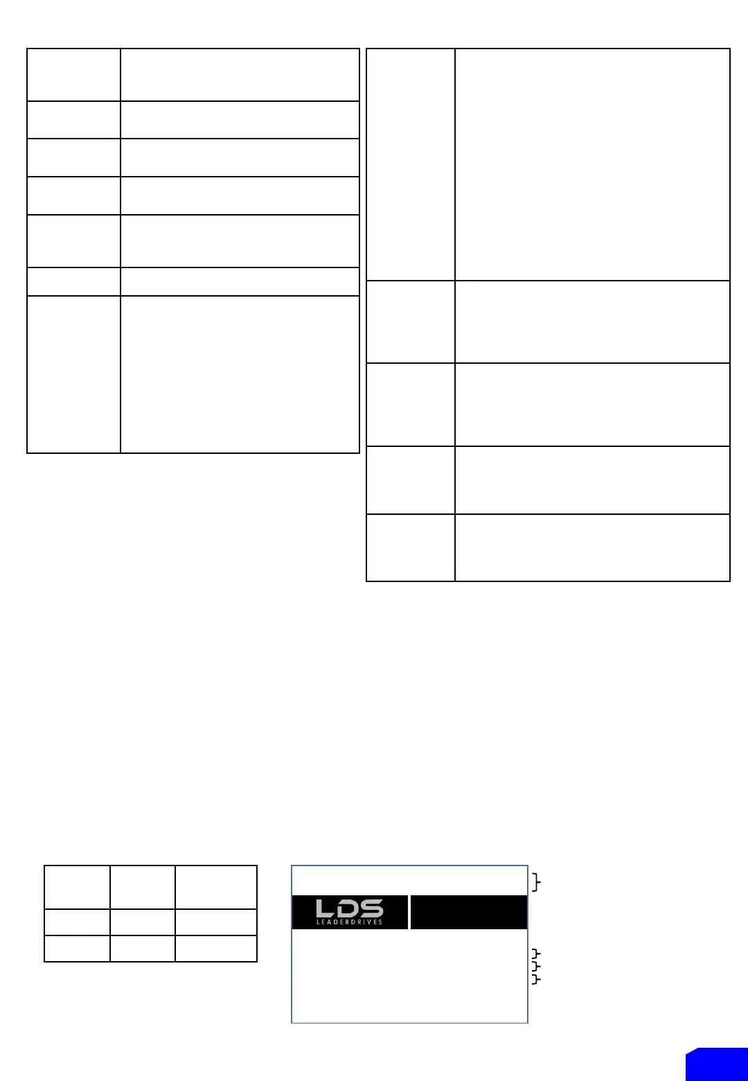
Serial Number
IGBT-K200
LDS Compact IGBT Inverter 200W
OVLP 150% S/N : DM15A2V242
Input : 1Ø 200V~240V 50Hz/60Hz 3.0A
Output : 3Ø 220V 0.1Hz~400Hz 1.5A
PGM: 0201-001(AZ055891) ISO 9001 IP20
www.leaderdrives.com
Leader Mechanical
& Electrical Co., Ltd
Model Number
Code
Power
(Watt)
Horse
Power
K100 125W 0.17HP
K200 200W 0.25HP
P 5
Input Power Voltage
Output Power Voltage
Voltage vector sinusoidal PWM control
(V/F control)
Switching frequency : 800~16kHz
Digital Command : 0.01Hz
Analogue Command: 0.06Hz / 60Hz
150% of rated output current for 1
minute
Start/Stop Braking Time: 0 ~ 60.0 second
Stop Braking Frequency : 0.1Hz ~ 60Hz
Braking Ability: 0~150% of rated current
adjusting V/F pattern according to the
load condition)
Square of 1.5, 1/7 and 2 curves.
V/F pattern (2 V/F points)
Output voltage adjustment of V/F
pattern.
(Variable voltage adjustment of V/F
pattern for acceleration and
deceleration).
Automatic operation for energy
Automatic torque compensation
Automatic adjustment for output voltage
stability
Automatic adjustment of switching frequency
•
Slip compensation / Counter function
Restart after instantaneous power
-torque detection
•
Jump frequency
•
and lower limits of output
-preset speeds
•
S-curve acceleration &
Frequency
Setting
Signal:
Operation panel (including KP
Analogue Signal: (DC 0 ~ 10V) / 0~100%
Digital Signal: Jog speed, 8
Modbus (RS485) Communication
Operation panel (including KP
RUN / STOP
Digital Signal: FWD (forward) / REV (reverse)
rotation control
Modbus (RS
3 programmable input terminal: X1~X3
Response time (1~255, unit 1ms)
Refer to the F5.19~F5.21 functions setting
description.
1 set of analogue input: VI (DC 0 ~ 10V)
Analogue filter (0~255, unit 5ms), the dead
band of analogue frequency, gain and bias are
adjustable
GENERAL SPECIFICATIONS / CONTROL CHARACTERISTICS


 To Next Page