EasyManua.ls Logo

Leader Electronics Corp. LPS-160A - Page 16

Leader Electronics Corp. LPS-160A
21 pages
Print Icon
To Next Page IconTo Next Page
To Previous Page IconTo Previous Page
Loading...
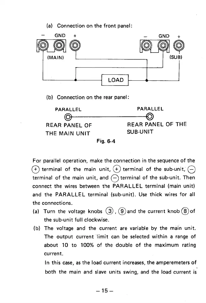
(a)
Connection on the
front
panel:
GND
+
GND
+
~
(SUB)
(b) Connection
on
the
rear
panel:
PARALLEL
PARALLEL
@~----------@
REAR PANEL OF REAR PANEL OF THE
THE
MAIN
UNIT
SUB-UNIT
Fig.
6-4
For parallel operation-,
make
the connection
in
the
sequence
of
the
0 terminal
of
the main
unit,
G)
terminal
of
the sub-unit; 8
terminal
of
the main
unit,
and
8 terminal
of
the sub-unit. Then
connect the wires between the
PARALLEL
terminal (main unit)
and
the
PARALLEL
terminal (sub-unit).
Use
thick wires
for
all
the connections.
(a)
Turn the voltage knobs
@,@and
the current knob
@of
the sub-unit full clockwise.
(b) The voltage
and
the current
are
variable by the
mai"n
unit.
The output current
limit
can
be
selected within a
range
of
about 10
to
100%
of
the double
of
the maximum rating
current.
In this
case,
as
the load current
increases,
the amperemeters
of
both the main
and
slave
units swing,
and
the load current
is
-15-