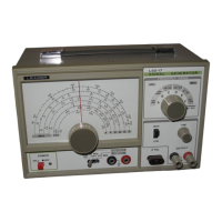
INPUT-OUTPUT
XTAL socket
POWER switch
Pilot lamp
Mode switch
For
insertion
of
quartz crystal,
1-15MHz,
in Type FT-243 holder.
For
turning
on
the
AC
power.
Indicates when AC power
is
on.
EXT
MOD:
For
modulation
of
carrier with an external source.
INT
MOD:
Use
of
internal 1kHz
for modulation or external cir-
cuit testing.
XTAL OSC: Crystal oscillator out-
put;
frequency depends
on
crys-
tal used.
For
external modulation .input or
output
from internal 1kHz oscilla-
tor.
@ FINE control Continuous
RF
output
voltage ad-
juster.
RF
LOW-HIGH switch Sets the
RF
output
level;
at
LOW,
output
is
lowered
by
1/10.
OUTPUT terminals
For
connection to
RF
output
leads.
2.2 Circuit Design
The circuits which compose the LSG-17 will be described
with reference to the functional block diagram and components
designated
on
the schematic.
A.
RF
Circuit.
The
RF
oscillator uses an IC, IC102, in
the
Colpitts
circuit to generate frequencies from 100kHz
to
150MHz
on
fundamentals. The frequency
of
operation
is
set with
the
FREQ RANGE switch and the tuning dial. Calibration
-3-