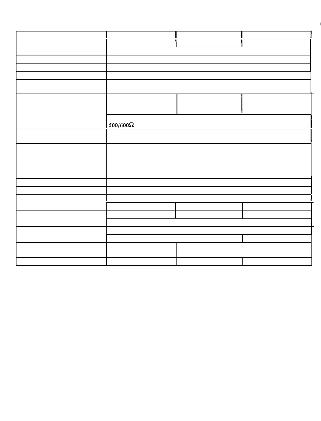
TECHNICAL SPECIFICATIONS
I
CT35
I
CT60
I
CT100
I
POWER OUTPUT (RMS at 1000Hz)
FREQUENCY RESPONSE
REGULATION
35 watts
I
60 watts
I
100 watts
@
less than 2% total harmonic distortion
50Hz to 15kHz ±2dB
2
dB
HUM
&
NOISE (below rated output)
MIC, 60
dB
for both low and high impedance; AUX 70
dB;
Fundamental, 80
dB
SENSITIVITY
(for rated output)
Hi Z MIC, 3 mV; Low Z Bal MIC, 0.3
mV;
Low Z Unbal MIC 0.3 mV; Bridging Input,
30 mV; AUX 150
mV
OUTPUTS
4, 8,
16
ohms
8,
16
ohms
25V CT
25V
CT
7ov 7ov
I
4, 8,,
16
ohms
25V
CT
7ov
I
Bridging, 30
mV;
Tape, 0.68 V. TAPE/BOOSTER/BRIDGING outputs,
500/6OOa telephone line input or output with WMT-i optional accessory.
I
OUTPUT CONNECTIONS
I
2 Quick disconnect type sockets with plugs provided, in addition to screw-type
terminals, tape/booster jack, and provisions for WMT-1.
I
INPUTS
CONTROLS
4 Hi Z MIC inputs, each convertible to Low Z Bal or Unbal MIC; 2 AUX inputs with
fader control; MIC 1
&
4 convertible to MAG input; Bridging input; 500/600 ohm
telephone line with optional WMT-1 accessory; 3 inputs for remote volume control.
4 MIC Volume, AUX 1, AUX 2-fader, MASTER VOLUME, 5 Equalizer Filter Slide
Controls. 1
Compressor.
1 Power Switch.
FILTERCONTROLACTION ±
10
dBB
variationatthefollowingfrequencies:
80Hz,300Hz,
1
kHz,
3
kHz,
10
kHz.
COMPRESSION
5 milliseconds attack time, 2 seconds decay time, max. compression 30
dB
LINE FUSING
I
Resettable Circuit Breaker
I
SEMICONDUCTORS
POWER CONSUMPTION
0.93 A Hold
1.65 A Hold 2.5 AHold
18
silicon transistors 18 silicon transistors
20
silicon
transistors
2 Zener Diodes; 8 Silicon Diodes (10 in
CTl00)
120 V AC,
50/60
Hz
DIMENSIONS
SHIPPING WEIGHT
0.86A, 96W
16-3/8”W
x
12¾”D
x
4¾”H
(41.6cm x 32.4cmx12.lcm)
19 lbs. (8.6 kg)
1.6A,
170w
2.9A, 300W
16-3/8”W
x
13 3/4”D
x
4 3/4”H
(41.6cm x
34.9cm
x 12.lcm)
221bs. (9.9 kg)
26 lbs. (11.8 kg)
INPUT CONNECTIONS
HIGH IMPEDANCE MICROPHONES: The amplifier is
shipped in a configuration for direct connection of high
impedance microphones (50k ohms) to the four MIC input
receptacles of the amplifier. The microphone lead should be
a single-conductor shielded cable under 35 feet long and
terminated in a Cannon XLR-311C connector
(Bogen
Part
No. 85-0124-01) as shown in figure 2.
In the event jumpers on the printed circuit board have
been rearranged and must be returned to the configuration
for direct connection of high impedance microphones,
connect the two jumpers involved as follows: the first
jumper between terminals 11 and 19, and the second
be-
tween 8 and 18. Three jumpers are not involved and are
stored by connecting both ends to an assigned terminal: the
first jumper on terminal 20, the second on 24, and the third
on 25.
BALANCED LOW-IMPEDANCE MICROPHONES:
Low-
impedance accessory transformers are required to permit
the amplifier to accept inputs from microphones rated from
50 to 600 ohms. Before connecting microphone, insert
appropriate plug-in transformers and reset jumpers adjacent
to transformer sockets as described in the Accessories
sec-
tion. Use a two-conductor shielded cable for the
+
micro
phone lead, terminated in a Cannon XLR-311C connector,
as shown in figure 3.
,
-2-
 Loading...