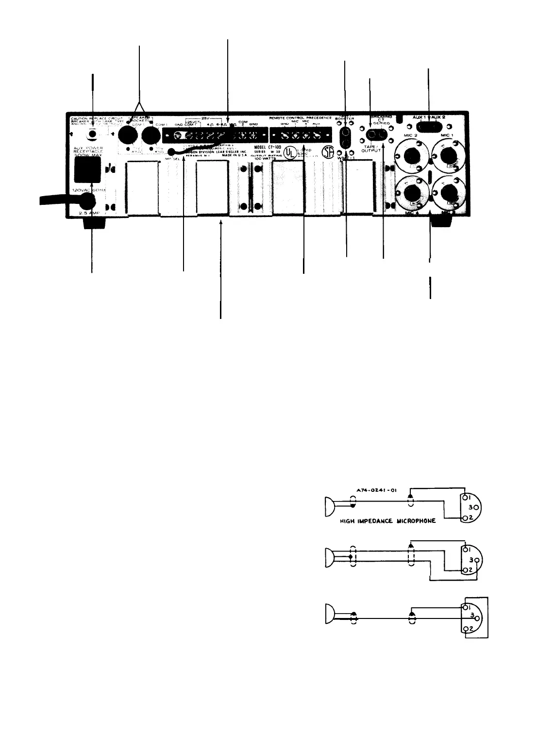
SPEAKER
OUTPUT
SOCKETS
TERMINALS
CIRCUIT
TAPE/BOOSTER
AUX
BREAKER
TAPE
INPUTS
I
OUTPUT
I
I
I
I
I
WMT-1
OUTPUT
I I
AUX
POWER
IMPEDANCE
REMOTE/PRECEDENCE
SELECTOR
TERMINALS
BRIDGING
I
I
MIC INPUTS
Note:
Heat sink for Model CT-35
HEAT SINK
is an aluminum plate.
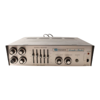
Figure 1
-
Rear Panel, CT-100
UNBALANCED LOW IMPEDANCE MICROPHONES:
Jumpers with push-on connector lugs are mounted on the
printed circuit board assembly for use in converting the
MIC input channel circuits. See note 4 on the schematic
diagram, figure 6. To convert MIC 1 and 4 for unbalanced
low impedance use, connect jumper between pins 20 and
2 1; to convert MIC 2 and 3, connect jumper between pins
25 and 26. As shown in figure 2, connect a jumper between
terminals 1 and 2 of the connector and wire microphone to
pin 3 of the plug.
AUXILIARY INPUTS: Two auxiliary inputs are provided
for high-level, high impedance inputs. these may be used to
connect a radio tuner, tape recorder, or turntable utiliz-
ing a ceramic cartridge. An input signal of 0.15 volts is
required to obtain full output from the amplifier.
Use single-conductor shielded cable terminated in an
RCA phono plug for connecting auxiliary component. If
hum is experienced after making connections, run a ground
wire between the chassis of the auxiliary unit and the GND
terminal on the amplifier.
BRIDGING: The amplifier may be bridged to a second
Bogen
CT amplifier to double the number of inputs. Con-
nect a single-conductor shielded cable, terminated in an
RCA phono plug at each end, between the rear panel
BRIDGING receptacles of the two amplifiers. Any input to
either amplifier will then be fed through and available at
the output of both amplifiers. The amplifiers must each
When two amplifiers are bridged together,
any adjustment of the MASTER, COM-
PRESSION or Acoustic Equalizer controls in
one amplifier will not affect the output of
the other amplifier.
:
(CONNECTION
SAME
FOR
MAG
PHONO)
XLR-311C
BALANCED
LOW IMPEDANCE MICROPHONE
XLR-311C
J
2
UNBALANCED
LOW IMPEDANCE MICROPHONE
XLR-311C
feed separate speaker systems.
Figure 2
-
Connecting Microphone Cable Connector
-3-


 To Next Page
 Loading...