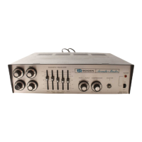
MAG PHONO: The output of a phonograph employing a
magnetic cartridge may be connected to the MIC 1 and 4
receptacles on the rear panel. Use a single-conductor
shield-
ed audio cable terminated in a Cannon XLR3
11C
connec-
tor as shown in figure 2 (connections same as high im-
pedance mic). A magnetic tape head may also be connected
in this manner.
Connect a single conductor shielded cable, terminated in
an RCA phono plug at each end, between the rear panel
BRIDGING receptacles of both amplifiers. This assures that
any input will have equal amplification.
To provide the necessary equalization for magnetic
phono and tape head inputs, the Berg terminal jumpers on
the printed circuit board must be connected as indicated in
note 3 on the schematic diagram. Connect a jumper be-
tween pins 21 and 22 and between pins 23 and 24.
AMPLIFIER 1
GND
COMI
25VCT
AMPLIFIER 2
GND
COMl
25VCT
OUTPUT CONNECTIONS
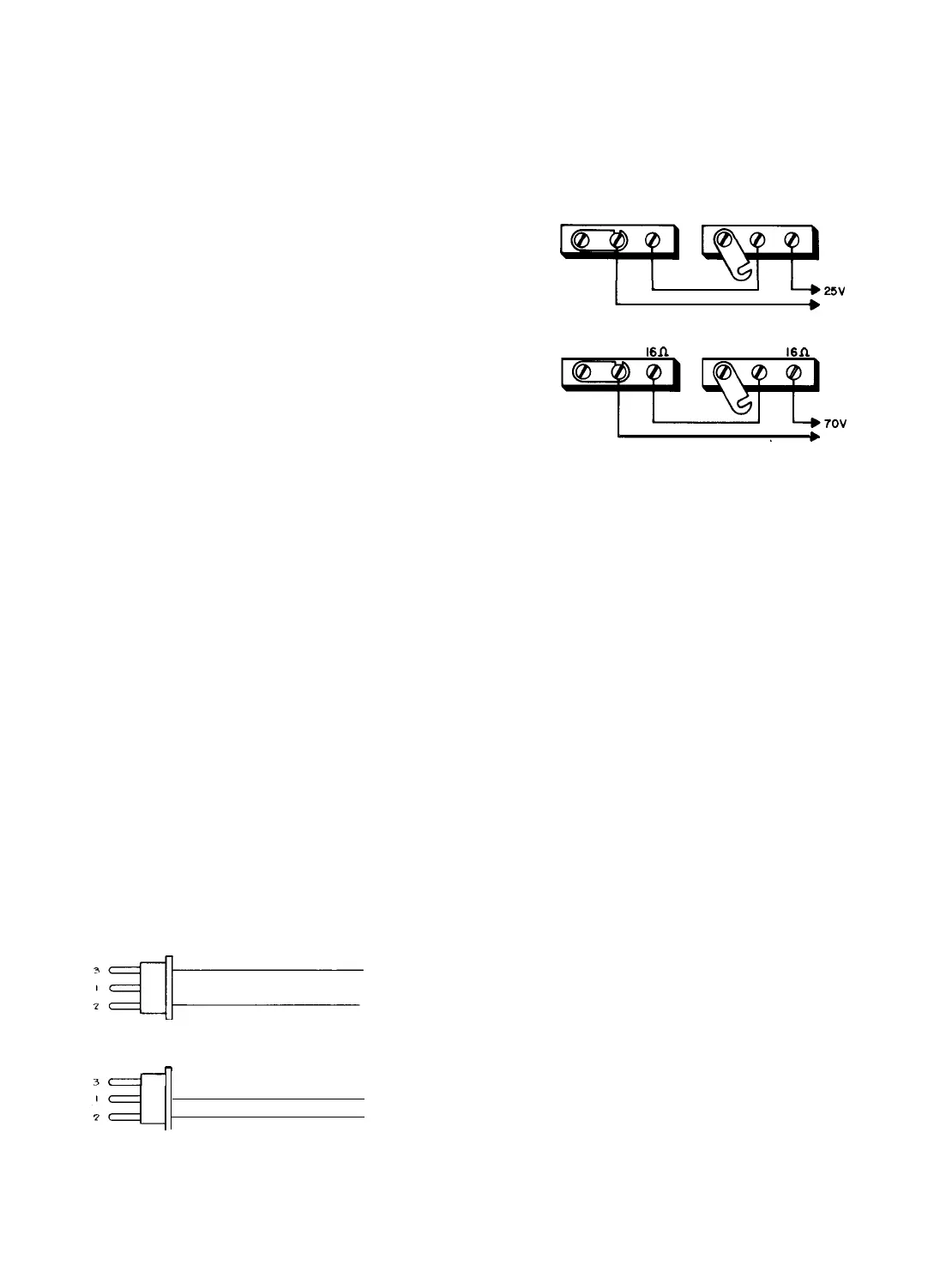
SPEAKERS: For installations where speakers will be con-
nected permanently, output connections are available on
the terminal strip at the rear of the amplifier for 4, 8, and
16 ohm speakers and
25volt
lines. Connections may be
made for an unbalanced line or for a balanced line with or
without center-tap grounding. Make speaker line connections
as shown in Table 1.
Impedance indicated in Table
1
is also available at two
speaker sockets on the rear panel. Two quick-disconnect
plugs (Bogen 85-0147-01) are furnished with the amplifier
to make connections to these sockets. Wiring of the speaker
output plug is shown in figure 3. When the speaker sockets
are used, connect the wired plug to either socket. For
un-
1
L+25V
ALL UNITS
b
AMPLIFIER 1
AMPLIFIER 2
GND COM 1
l6n
GND COM 1
16n
CT60 AND CT
100
A74-2031-01
Figure 4
-
Connecting Amplifiers in Series
balanced. 4, 8, 16 ohms
and 25-volt
operation, attach the
impedance selector lead to the speaker system impedance
Both amplifier tone and master volume controls must be
at the same setting to assure that each amplifier will share
terminal, and leave the link connected between COM
1
and
GND terminals. A balanced output is available by removing the
the load equally.
link.
For 70 volt constant voltage systems, see Table 1. For
detailed information see installation manual No.
54-5001,
furnished with the amplifier.
To minimize shock hazard, Class I wiring as
defined in local building codes should be
used for 70-volt outputs. All other outputs
may use Class 2 wiring.
CONNECTING AMPLIFIERS IN SERIES: Pairs of Bogen
CT amplifiers of the same power rating can be connected in
series to effectively double the power output into the same
speakers. See figure 4 for connection diagram. Be certain to
remove the link between
COM 1 and GND of amplifier No.
2.
FOR 70V
OPERATlON
zil-J=
FOR 25V OPERATION
OR SELECTED IMPEDANCES
-!
3c---1-
Figure 3-Speaker Output Plug Wiring
TAPE/BOOSTER OUTPUT: The amplifier may be used to
drive a tape recorder or a booster amplifier. Connect a
patch cord with an RCA phono plug from the TAPE/
BOOSTER jack on the rear panel of the amplifier to the
input of the tape recorder or booster amplifier. The output
at this jack is controlled by the amplifier’s volume and
equalization controls.
TAPE OUTPUT: A tape recorder may also be driven from
the TAPE OUTPUT jack on the amplifier. In this case, the
output is not subject to the master volume and equalization
settings of the amplifier and is controlled at the tape
recorder. A patch cord terminated in an RCA phono plug is
connected between the TAPE OUTPUT jack on the ampli-
fier and the input of the tape recorder.
WMT-1 OUTPUT: This receptacle is used to accommodate
a Bogen accessory which provides connections to a
500/
600-ohm telephone line.
ACOUSTIC EQUALIZER: The Acoustic Equalizer permits
you to “tune” the amplifier to the room in which the
sound system is used, so that the amplifier will operate at a
substantially higher output before acoustic feedback oc-
curs. Five slide controls, located on the front panel, boost
or attenuate the output at five selected frequencies-80 Hz,
300 Hz, 1 KHz, 3
kHz,
and 10
kHz.
Varrying room acous-
tics or microphone placement may cause feedback or howl-
ing at or near some of these frequencies. If so, feedback can
be greatly attenuated by setting the slide control for that
particular frequency as described below.
-4-


 To Next Page
 Loading...