21
ENGLISH
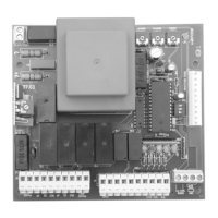
7) Definitions of Trimmers
RV1 - Pause
It defines the duration of the gate’s pause before automatic closure.
RV2 - M2 Delay
It defines the delay between the first wing’s (M1) and the second wing’s (M2) start during the closure phase.
RV3 – Work time
It defines the motors’ work time during the opening or closure phases.
8) Definitions of Dip Switches (Selection of Programs)
SW1 - Dip switch 1
It chooses whether the unit will operate in step-by-step mode or in automatic mode.
ON =Automatic OFF=Step by step
SW1 - Dip switch 2
It chooses whether the unit will operate in the mode determined by dip-switch 1 or in condominium mode.
ON=Codominium OFF=No effect
SW1 - Dip switch 3
It enables or excludes the kickback (during the opening phase with closed gate).
ON= Kickback enabled OFF=No effect
SW2 – Dip Fix
It determines the operation mode of the J7 auxiliary connector’s output.
Closed Dip fix = electrochain mode Opened Dip Fix = courtesy light mode
9) Definitions of Protection Fuses
F1 – Mains power fuse (5A)
It disconnects the electronic unit from the power supply mains in case of short-circuit or electric current consumption anomalies.
F2 – Low voltage fuse (2A)
It protects the electronic unit in case of short circuits or overcurrents on photo-cells, electric lock or any other accessory devices connected to the
24 Vac power supply.
10) Technical features
Power regulator
The electronic unit is pre-set for the optional connection of an accessory card called “power regulator”. By means of this card the power supplied to the
motors can be reduced.
Caution
: In case failure or anomaly of the power regulator card the motors may operate at their maximum power value. This is why n° 7 note
in the previous chapter “limits to use” must absolutely be put into practice.

 Loading...