LECTROSONICS, INC.6
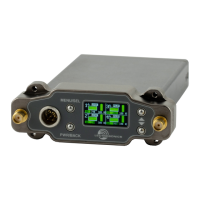
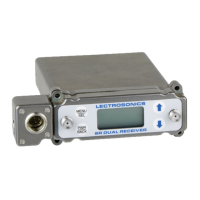
• Receiver Power Icon
changes to a plug icon
when external power is sup-
plied.
• Antenna Icons: Status of
the diversity system.
• RF Signal Strength Strip
Charts: RF signal strength
indicators.
• Channel Status Indicator:
Pilot tone, link and encryption
system status.
Navigating the
Menus
From the Main Window, press
MENU/SEL to enter the menu,
then navigate with the UP and
DOWN arrows to highlight the
desired setup item. Press MENU/
SEL to enter the setup screen for
that item. Refer to the Menu Map
on the following pages.
Operating
Instructions
The following checklist includes
the minimum required settings to
start using the receiver:
• Install either a battery sled,
camera slot adapter or
other power source via EXT
BOTTOM PLATE.
• Connect power to the re-
ceiver.
• Set the COMPAT (compatibil-
ity) mode for the transmitters
to be used.
• Find clear operating frequen-
cies for one or both receivers
using SmartTune or manual
scanning.
• Set transmitters on the
matching frequencies, manu-
ally or by using IR sync.
• Verify transmitters are set to
the same compatibility mode
as the receiver (see transmit-
ter manual).
• Adjust transmitter input gain
to match voice level and
mic position (see transmitter
manual).
• Adjust receiver output level
as needed for the camera or
mixer input level desired.