EasyManua.ls Logo

Lectrosonics SRc - User Manual

Lectrosonics SRc
36 pages
Print Icon
To Next Page IconTo Next Page
Loading...
SRc5P & SRc
Camera Slot Dual UHF Receiver
Featuring
Digital Hybrid Wireless
®
Technology
INSTRUCTION MANUAL
Rio Rancho, NM, USA
www.lectrosonics.com
Fill in for your records:
Serial Number:
Purchase Date:
U.S. Patent 7,225,135
Quick Start Summary
The following checklist includes the minimum required
settings to start using the receiver.
Install either a battery sled or camera slot adapter
kit (see pages 9-13).
Connect power to the receiver (see pages 11, 12,
14).
Set the DIVMODE for single or dual channel opera-
tion (see page 21).
Set the COMPAT (compatibility) mode for the trans-
mitters to be used (see pages 21).
Find clear operating frequencies for one or both
receivers (see page 24).
IMPORTANT:
FREQ.
WARNING
Performance will be degraded if
Receiver 2 is set 4.2 to 4.8 MHz higher
than Receiver 1. The LCD will also flash
this message periodically.
Set transmitters on the matching frequencies (see
transmitter manual).
Verify transmitters are set to the same compatibility
mode as the receiver (see transmitter manual).
Adjust transmitter input gain to match voice level
and mic position (see transmitter manual).
Adjust receiver output level as needed for the cam-
era or mixer input level desired (see page 20).

Table of Contents

Other manuals for Lectrosonics SRc

Question and Answer IconNeed help?

Do you have a question about the Lectrosonics SRc and is the answer not in the manual?

Summary

Quick Start Summary

Digital Hybrid Wireless Technology

Model Differences

SRc Receiver

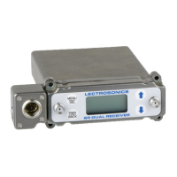
Basic receiver with audio outputs on the rear panel only.

SRc5 P Receiver

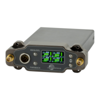
Offers an additional front panel audio output for specific camera setups.

General Technical Description

SmartDiversity Operation

Antenna phase combining for diversity reception based on RF level.

Ratio Diversity Operation

Blends audio from both receivers for a single output with improved SNR.

Three Block Tuning Range

RF Front-End with Tracking Filter

IF Amplifiers and SAW Filters

Digital Pulse Counting Detector

DSP-Based Pilot Tone System

SmartSquelch Feature

Turn On and Turn Off Delays

Test Tone Generator

LCD Display Overview

Smart Noise Reduction (SmartNR)

Front Panel Controls and Functions

Audio Outputs

Describes the audio output options on the rear and front panels.

LCD Screen

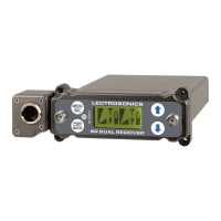
Describes the backlit LCD display for setup and monitoring.

MENU;SELECT Button

Used to select menu items and enter setup screens.

PWR;BACK Button

Powers the unit on/off and navigates menus.

IR (Infrared) Sync

Used for quick setup with transmitters offering IR sync.

UP;DOWN Arrow Buttons

Used to select options and adjust values in setup screens.

Rear Panel and Adapters

Camera Slot Adapters

SRSUPER Adapter Installation

Instructions for installing the SRSUPER adapter onto the receiver.

SRSNY Adapter Installation

Instructions for attaching the SRSNY adapter to the camera body.

Adapters for Stand-Alone Use

SREXT Adapter Kit

Kit includes a rear panel with TA3 jacks and a power jack.

SRHARNESS Adapter Kit

Kit for portable "bag systems" with balanced output cables.

Installing Rear Panel Adapters

Replacement Screw Kits

Battery Adapters

SRBATTSLEDTOP Adapter

Top battery sled adapter for video camera batteries.

SRBATTSLEDBOTTOM Adapter

Bottom battery sled adapter for video camera batteries.

SR9 VBP 9 Volt Battery Case

Optional 9 volt battery case for sled adapters.

Installing the SRBATTSLED

Battery Life Estimates

SR9 VBP 9 Volt Battery Adapter Details

SRSLEEVE Mounting Adapter

SRHARDWARE Mounting Adapter Kit

Audio Output Cables and Connectors

MCSR5 PXLR5 P Cable

Right angle TA5F plug to 5-pin XLR cable.

MCSR5 PXLR2 Cable

Right angle TA5F plug to two 3-pin XLR cable.

MCSRPT Cable

TA3 female to stripped and tinned wires cable.

MCSRXLR Cable

TA3 female to XLR male 3-pin cable.

MCSRTRS Cable

3.5 mm TRS plug to two TA3 connectors cable.

RATPAC Adapter Kit

External Power Supply Unit

External Power Cables

Mounting and Orientation

Antenna Orientation for Optimal Signal

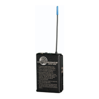
Proper antenna placement and orientation are crucial for signal reception.

AMJ Rev. A Jointed Antenna

AMJ Kit Cutting Template

Template and instructions for cutting the AMJ antenna whip to length.

LCD Main Window Indicators

Pilot Tone Indicator

Shows the status of the pilot tone from the transmitter.

Channel Mute Indicator

Indicates when a receiver's audio output is muted.

Antenna Phase Indicator

Shows antenna phase switching status in SWITCHING DIVERSITY mode.

RF Level Indicator

Displays the strength of the incoming RF signal.

Audio Levels Indicator

Shows the audio level (modulation) of the received signal.

Battery Levels Indicator

Displays the transmitter's battery condition.

Navigating the LCD Interface

Main Window Operation

Frequency Screen Operations

Setup Screens Navigation

Locking and Unlocking Front Panel Controls

LCD Backlight Setup

Menu Item Descriptions

LEVEL Setting

Adjusts the audio output level in dBu.

DEFAULT Setting

Restores the factory default settings.

LOCALE Setting

Affects C2 band coverage based on locale setting.

SMARTUNE Function

Scans for and finds clear operating frequencies.

IR SYNC Procedure

SCAN Function for Clear Frequencies

DIVMODE Selection

TALKBACK Function

COMPATibility Modes

TUNING Modes and Selection

STEPSIZE Setting

SmtNR Noise Reduction Settings

PHASE Audio Polarity Setting

TXBAT Transmitter Battery Settings

MIXTRIM and MIXMODE

TONE Test Signal

Front Panel Shortcuts

Accessing Block 606 Mode

Scanning for Clear Frequencies

Scan Window

Displays RF activity levels and selected frequencies during a scan.

Zoom View Window

Provides a zoomed view for fine-tuning frequency selection.

Pre-coordinated Frequencies

Frequency Coordination Explained

Multi-channel System Checkout Procedure

Troubleshooting

Initial Power On Issues

Addresses issues with the LCD display not being active or lit.

Internal Error Messages

Indicates an internal error requiring factory assistance.

Frequency Check Warning

Warns of a strong RF signal not centered on the channel.

Pilot Tone Squelch Issues

Covers issues with pilot tone presence, absence, or flashing.

Noise and Pilot Tone Bypass

Indicates the pilot tone bypass has been activated.

Audio Present Without Pilot Tone

Discusses scenarios where pilot tone is absent but audio is present.

RF Signal Strength Problems

Addresses issues related to weak RF signals or no RF signal.

Audio Signal Quality Issues

Covers problems with poor signal-to-noise ratio.

Audio Distortion and Response

Addresses issues related to audio distortion and bad frequency response.

Specifications and Features

FCC Compliance Notice

Service and Repair

Returning Units for Repair

Outlines the steps for sending equipment back for repair.

Attestation of Conformity

Declaration of Conformity

Limited One Year Warranty

Lectrosonics SRc Specifications

General IconGeneral
Number of Channels2
Tuning Steps25 kHz
ModulationFM
Sensitivity-100 dBm for 12 dB SINAD
Adjacent Channel Rejection> 70 dB
THD< 0.5%
Dynamic Range> 100 dB
Frequency Range470 to 608 MHz
Operating TimeUp to 8 hours
Power2 AA batteries
Power Requirements6 to 18 VDC

Related product manuals