Do you have a question about the Lectrosonics UCR100 and is the answer not in the manual?
Overview of the receiver's technical design, microprocessor control, and frequency operation.
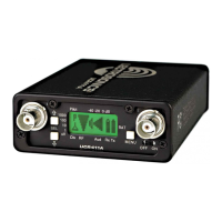
Highlights the receiver's multi-frequency capability, microprocessor control, 256 frequencies, and compact design.
Explains the dual-band companding system for improved audio quality and reduced distortion.
Visual representation of the receiver's internal electronic components and signal flow.
Describes the pre-emphasis/de-emphasis technique used to enhance the signal-to-noise ratio.
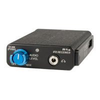
Explains the function of the -20 dB and 0 dB LEDs for monitoring audio signal modulation.
Describes the function of the switch to turn the receiver on or off.
Details the power LED's behavior for indicating power status and battery condition.
Explains the RF LED's function in indicating signal strength and transmitter status.
Describes the 3.5mm mini phone jack for audio output and its compatibility.
Details the control for adjusting the receiver's audio output level to match equipment inputs.
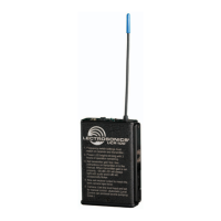
Describes the fixed 1/4 wavelength flexible non-removable antenna.
Explains the rotary switches used to adjust and match the receiver's operating frequency.
A quick guide to understanding the meaning of the RF, Power, and Modulation LED indicators.
Instructions on battery types, installation, and replacement for optimal operation.
Step-by-step guide on how to return the unit for repair service, including contact information.
| Number of Channels | 1 |
|---|---|
| Tuning Steps | 25 kHz |
| Modulation | FM |
| Dynamic Range | >100 dB |
| Power Requirements | 12-18 VDC |
| Receiver Type | Diversity Receiver |
| RF Sensitivity | -100 dBm |
| Image Rejection | > 80 dB |
| Spurious Rejection | > 80 dB |
| Audio Output | Unbalanced |
| THD | < 0.5% |
| Signal-to-Noise Ratio | > 100 dB |
| Power Supply | External |