Do you have a question about the Lectrosonics IFBT4 and is the answer not in the manual?
Overview of the IFBT4 transmitter, its lineage, and key features.
Explanation of the proprietary system for enhanced audio quality and compatibility.
Details on the XLR connector and input sensitivity settings via DIP switches.
Visual representation of the unit's internal components and signal flow.
DSP-controlled audio limiter for overload protection and transparent operation.
Functions related to companding and noise reduction for clear IFB audio.
System for distinguishing valid IFB signals from RF interference.
Synthesized frequency selection for avoiding interference in various applications.
Circuitry that adds delays to prevent clicks and thumps during mode changes.
Oversees system operations, including RF frequency and DSP functions.
High RF power level and spectral purity for a clean, reliable signal.
Description of the 50 Ohm BNC connector for standard antennas.
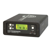
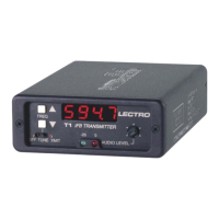
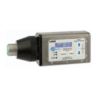
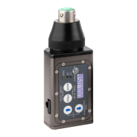
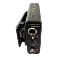
Layout and identification of front panel controls and displays.
Functionality of the main power and mode selection switch.
Display sequence shown when the unit is powered on.
Explanation of the audio level meter and its indicators.
How to view and select operating frequencies.
Procedure for setting the audio input gain level.
Entry point to various configuration settings.
Configuration of low-frequency audio response settings.
Selection of compatibility modes for different receivers.
Options for selecting factory or user-defined frequency groups.
Method to prevent accidental changes to settings.
Visual guide to navigating the unit's menu system.
Behavior of frequency selection in Normal and Group modes.
How to manage custom frequency groups with entries.
Steps to add or remove frequencies from user groups.
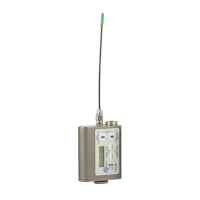
Details of the standard XLR female input connector.
How DIP switches configure input sensitivity and pin functions.
Specifications and type of the external power connector.
Information on the BNC antenna connector.
Guidance on setting audio levels and understanding limiting.
Possible causes and solutions for a dead display.
Troubleshooting steps for lack of transmitter modulation.
Diagnosing issues when no signal is received by the receiver.
Causes for low audio output when the receiver is powered on.
Identifying and resolving causes of distorted audio output.
Resolving issues related to audio hiss, noise, or signal dropouts.
Causes for blinking antenna icons or hex codes in windows.
Color codes and lengths for antennas matching frequency blocks.
Procedures and contact details for sending equipment for service.
| RF Output Power | 50 mW |
|---|---|
| Battery Life | 8 hours |
| Frequency Stability | +/- 0.002% |
| Frequency Range | 470 - 608 MHz |
| Modulation | FM |
| Spurious Rejection | >60 dB |
| Battery Type | AA |
| Operating Temperature | -10°C to 50°C |