Wiring Connections ALC-1
For ALC-1 (single actuator, single station display only)
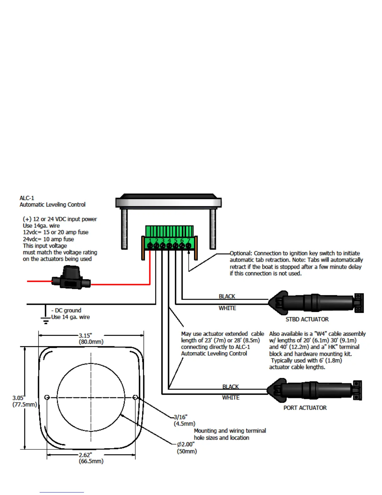
• Wiring Display Panel:
1. Refer to wiring diagram as shown below for the ALC-1 wiring connections.
2. The red (+12vdc or +24vdc) wire from the boat’s fuse panel and black battery negative wires should be a
minimum size of 14 AWG (2.5mm²).
3. Important: DC voltage source connected to ALC switch must match actuator voltage (first letter in
actuator serial A, C or S =12vdc, B or D = 24vdc).
4. Optional: Terminal 7 may be connected to ignition key run position to automatically retract the tabs
when key is switched to OFF. The tabs will automatically retract if this option is not used after the
control senses the boat is off plane for a few seconds.
7