2000 Hour Intervals
Change tandem oil
Grease tandem pivots
Grease circle gearbox
Change differential oil
Change planetary hubs oil
Change hydraulic oil
SCHEDULED MAINTENANCE
PROCEDURES
AS REQUIRED MAINTENANCE PROCEDURES
Clean and Tighten Battery Terminals
WARNING: Battery gas can explode. Keep
sparks and flames away from bat-
teries. Always remove grounded (-)
battery clamp first and replace last.
The batteries are located in a compartment on the
left side of the machine.
1. Disconnect battery clamps, grounded clamp first.
2. Clean terminal and clamp with a stiff brush.
3. Install and tighten clamps, grounded clamp last.
Check Tire Pressure
WARNING: Explosive separation of a tire and
rim parts can cause serious injury
or death.
• DO NOT operate with low pressure, cuts,
bubbles, damaged rims, or missing wheel studs
and nuts.
• Always maintain correct tire pressure. DO NOT
inflate tires above the recommended level.
• When inflating tires, use a clip-on chuck and
extension hose long enough to allow you to stand
to one side and NOT in front of or over the tire
assembly.
Check tire pressure with an accurate gauge having
1 PSI (6.9 kPa) (0.07 bar) graduations.
1. Shut off air supply to hose.
2. Move gauge hand to correct pressure.
3. Lock air chuck on tire valve.
4. Turn on air supply. Stand to front or rear of
tire when air is added. Inflate tires to 35 PSI
(241 kPa) (2.41 bar).
NOTE: Tire pressure may need to be changed
for specific working conditions. Refer
to manufacturers information.
5. After tire is at correct pressure, shut off air
supply. Release chuck.
6. Inspect tire for damage.
Belt Inspection and Adjustment
1. Check belt regularly for wear. Replace if
defective.
2. Check tension of belt closest to fan midway
between pulleys. Apply a force of 20 lb. (90 N)
and check for a deflection of ¾ in. (19 mm).
3. If deflection is not within specifications, loosen
alternator mounting cap screw.
4. Tighten capscrews to 20 ft. lb. (27.12 N•m).
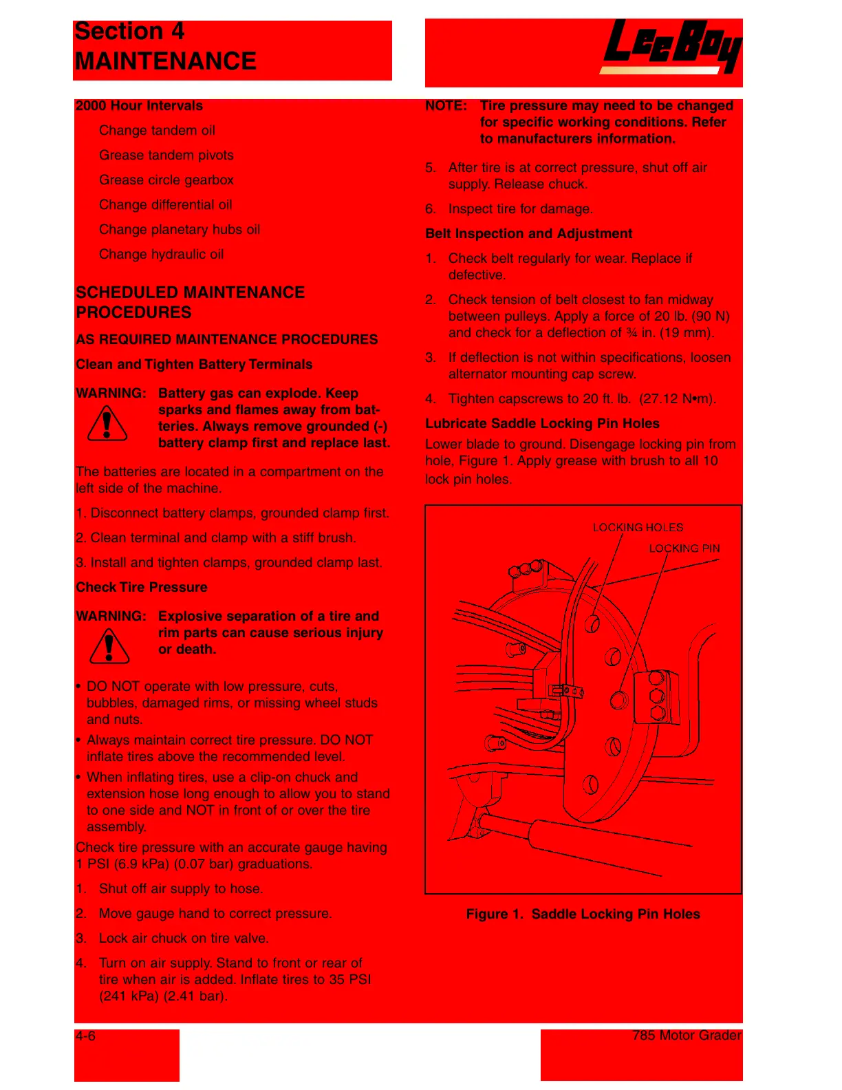
Lubricate Saddle Locking Pin Holes
Lower blade to ground. Disengage locking pin from
hole, Figure 1. Apply grease with brush to all 10
lock pin holes.
Figure 1. Saddle Locking Pin Holes
Section 4
MAINTENANCE
4-6
785 Motor Grader
Courtesy of Machine.Market
 Loading...