Do you have a question about the Leetro MPC6535 and is the answer not in the manual?
Install LaserCut program on your computer by running setup.exe and following instructions.
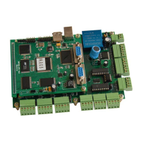
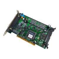
Mount the MPC6535 controller board firmly in the machine and ensure proper grounding of the machine housing.
Details the physical size specifications of the MPC6535 controller board in millimeters.
Defines the function of each pin on the MPC6535 controller, including power, I/O, and axis signals.
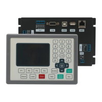
Illustrates the overall control system architecture, connecting the MPC6535 to drives, power supplies, and peripherals.
Details the electrical interface circuits for various functions like pulse/dir output, input/output ports, and laser control.
Diagram of the Pulse and Direction output port circuit for motor control.
Circuit diagram for the input ports, showing how external signals are received by the MPC6535.
Circuit diagram for the output ports, illustrating how the MPC6535 controls external devices.
Explains the circuitry for firing the laser, with active-low and active-high configurations.
Details the Pulse Width Modulation (PWM) circuit for controlling laser power.
Describes the DAC interface for controlling laser power output via an analog signal.
Key instructions for correctly wiring the MPC6535 controller, including power and signal connections.
Verify the versions of DLL, firmware, and hardware for the MPC6535 controller.
Settings in Lasercut53.exe for controller type, laser power, limits, and table size.
Process of downloading configuration files and resetting the control system.
Steps to input working files, edit diagrams, and make settings before starting.
Initiate the laser engraving and cutting operations after configuration.
| Model | MPC6535 |
|---|---|
| Input Voltage | 24V DC |
| Communication Interface | USB |
| Operating Temperature | 0°C to 45°C |
| Humidity | 10% to 90% (non-condensing) |