Do you have a question about the Leetro MPC6575 and is the answer not in the manual?
Introduces the MPC6575 controller for laser engraving and cutting, detailing its capabilities.
Illustrates the MPC6575 close-loop motion control system architecture with a diagram.
Details the dimensions and mounting specifications for the MPC6575 main board.
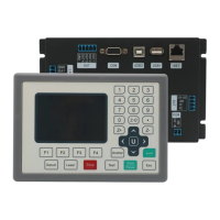
Provides dimensional drawings and mounting information for the PAD03 control panel.
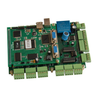
Describes the CPU board's USB interfaces and the J2 connector for HMI communication, including pin assignments.
Outlines the MC board's terminals for laser power, general I/O, axis control, encoders, and indicators.
Lists the specific pin assignments for the MPC6575/MC interfaces, categorized by function like POWER, INPUT, and OUTPUT.
Explains the functions of buttons on the PAD03 control panel, such as Datum, Laser, Stop, Test, Start/Pause, and Menu.
Details the RS232 connection wiring between the MPC6575/J2 and the PAD03 control panel.
Shows the initial startup message on the PAD03, including the version number.
Describes the PAD03 main interface, including file, speed, power, and time parameters, and editing procedures.
Guides on accessing the supporting interface and performing Z-axis operations like jogging and homing.
Details the processing interface, covering start/pause/stop functions and on-the-fly adjustments for speed and power.
Explains the process of downloading files from a USB stick to the MPC6575 using the PAD03.
States that the PAD03 directly displays error messages encountered during operation.
Describes the 'Soft Limit' error, its cause (exceeding worktable range), and the solution.
Details the 'Hardware Limit' error, its causes, and the solution to adjust laser head position.
Explains the 'No Memory Space' error, its causes (file quantity/size), and solutions.
Addresses errors from mismatches between configuration files and firmware, providing troubleshooting steps.
Discusses errors due to mismatched DLLs and firmware, recommending checks and re-downloads.
Explains errors from incompatible firmware and hardware, recommending firmware re-upgrade.
Lists causes for servo out-of-step alarms, including feedback, wiring, and parameter issues.
Covers the 'Speed-Zero Clamp' status and USB drive formatting requirements (FAT16).
Details requirements for touch screen programming and downloading, including cables and software.
Provides diagrams and pinouts for creating WeinView/EasyView programming and communication cables for touch screens.
Guides users on downloading touch screen programs using EasyBuilder software, including port selection and file opening.
Explains wiring for connecting two MT510 touch screens (host/auxiliary) to the MPC05.
Illustrates MT510 connections to PC/PLC and details DB25/DB9 connector pinouts.
Covers the operational aspects of the touch screen, including welcome and menu interfaces.
Shows the initial welcome screen for the laser system with company information.
Describes accessing the main menu interface on the touch screen.
Details the Laser interface for setting laser time and power, explaining parameter ranges and modes.
Explains the Jog Set interface for setting jog distance and controlling laser movement with direction buttons.
Describes accessing the main interface from the menu or other interfaces.
Details the work interface showing file, speed, power, time, and status, and explaining button functions.
Describes the status interface displaying messages for USB sticks or datum signals, and download progress.
Covers requirements for text display programming and downloading, including cables and software.
Provides wiring diagrams and pinouts for text display programming and communication cables.
Guides on using JB_HMI software to edit and download text display program files.
Shows the text display control panel layout and function buttons.
Details the text display main interface, explaining parameters and status.
Explains the Jog Set interface for editing jog distance and saving settings for laser movement.
Details the Laser Set interface for adjusting laser time and power, and explains laser beam generation modes.
Describes the work interface for editing speed/power and displays file, time, and status.
Covers the USB stick download interface, showing status messages like 'Remove USB Stick' and 'Download Completed'.
Specifies Modbus protocol settings (RTU, baud rate, data bits, parity) for HMI development.
Introduces tables detailing addresses and functionalities of PLC relays for HMI development.
Provides step-by-step instructions for upgrading MPC6575 firmware using a USB stick.
Guides on downloading processing and configuration files via USB stick, and notes on initial setup.
Explains how LED indicator lights on CPU and MC cards display system status and error codes.
Describes the function of LED indicators on the CPU and MC cards for various statuses.
Details the coding rules for error codes indicated by MC card LEDs.
Explains the functionality and instructions for using the USB stick indicator light signal to show download status.
Discusses PAD03 panel composition and customization, mentioning panel connection via 9-pin header.
Describes PAD03 components and refers to Chapter 5 for panel customization details.
Mentions connecting the control panel via a 9-pin header and refers to pin descriptions.
Explains the purpose of the process completion indicator light for operational safety.
Details the functionality of the process completion indicator light for confirming processing status.
Specifies using Pin OUT2 for the process completion indicator light signal.
Covers the blow-off functionality controlled via I/O interface for clearing heat and ash.
Explains the blow-off functionality controlled by I/O interface.
Details how Pin OUT1 controls the blow-off device based on commands and voltage.
Mentions setting the grade engraving power table according to laser power supply specifications.
Explains the soft limit functionality, which auto-detects processing file range after homing.
Describes controlling two laser heads independently by setting power mode and distance.
| Model | MPC6575 |
|---|---|
| Resolution | 0.001 mm |
| Type | Controller |
| Control Method | DSP Control |
| Communication Interface | USB |
| Control System | DSP |
| Supported File Formats | DST, PLT, BMP, DXF, AI |
| Humidity | 5-95% (non-condensing) |