Do you have a question about the LEGRAND DPX3 250 and is the answer not in the manual?
Details the available DPX3 product range with different breaking capacities.
Provides dimensional data for the fixed version, including a table of measurements.
Shows dimensional drawings for the fixed version with front terminals.
Illustrates dimensions for the fixed version with rear terminals.
Displays dimensional drawings for fixed versions with front motor operators.
Presents dimensional drawings for fixed versions with side motor operators.
Provides dimensional data and diagrams for the plug-in version.
Lists key electrical specifications like rated current, voltage, and impulse withstand.
Details technical characteristics for the switch components, including short-circuit ratings.
Specifies breaking capacity (Icu, Ics) for AC and DC voltage levels.
Shows current derating factors based on ambient temperature.
Presents power loss figures for different configurations and terminal types.
Details the short-circuit breaking capacity specifically for DC circuits.
Explains DC protection features and settings for earth leakage.
Lists derating information for operation at varying altitudes.
Provides details on opening and closing loads for the device.
Lists available shunt and undervoltage releases with specific part numbers.
Details direct and emergency rotary handles and their corresponding references.
Covers mechanical accessories like insulated shields and padlocks.
Lists accessories for connections, such as cage terminals and spreaders.
Describes bases for plug-in versions and related locking accessories.
Lists available motor operators (side/front) and locking accessories.
Details the rail fixing plate for mounting the DPX3 250.
Mentions the lithium battery used for device supply.
Displays the tripping time-current curve for cold and hot start conditions.
Shows the energy (I²t) curve as a function of short-circuit current.
Illustrates the restricted current curve, showing peak current vs. Icc.
Graph of earth leakage tripping time vs. current (instantaneous).
Graph of earth leakage tripping time vs. current (0.3s delay).
Graph of earth leakage tripping time vs. current (1s delay).
Graph of earth leakage tripping time vs. current (3s delay).
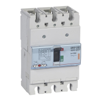
| Rated Current (In) | 250 A |
|---|---|
| Breaking Capacity | 36 kA |
| Voltage Rating | 415 V AC |
| Mounting | DIN Rail |
| Standards | IEC 60947-2 |
| Type | Molded Case Circuit Breaker |
| Number of Poles | 3 |