N
Nicole ElliottJul 28, 2025
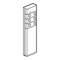
Why is the indicator light on my LEGRAND Medical Equipment hand-held remote control unit not working?
- JJessica HarmonJul 29, 2025
The indicator light on your hand-held remote control unit might not be working because the indicator light polarity on the magnetic socket is the wrong way round.