Do you have a question about the LEGRAND LEXIC 037 25 and is the answer not in the manual?
Explains automatic control of lighting based on light levels, with a 5-second switching delay to prevent flickering.
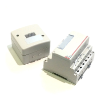
Instructions for taking apart the photocell unit, with numbered steps.
Details on mounting the photocell, including dimensions and IP rating.
Guidance on wiring the photocell, including electrical connections and maximum cable length.
Steps for reassembling the photocell unit after connection or maintenance.
Illustrates wiring configurations (Programmes 1-4) for the switch and photocell assembly.
Important warning about incorrect wiring potentially damaging the product.
Instructions on how to adjust the light sensitivity level using the potentiometer.
| Model | LEXIC 037 25 |
|---|---|
| Brand | Legrand |
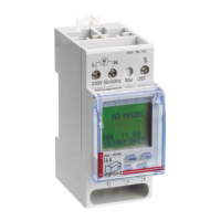
| Operating Voltage | 230 V AC |
| Frequency | 50/60 Hz |
| Switching Current | 16 A |
| Timing Range | 1 min to 168 hours |
| Number of Channels | 1 |
| Protection Degree | IP20 |
| Programming | Daily |
| Operating Temperature | -10°C to +50°C |
| Weight | 150 g |