Wattstopper
®
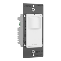
DLM Wired Standard Occupancy Sensor Switches
Quick Start Guide • Guide de démarrage rapide • Guía de inicio rápido
No: 32730 – 12/23 rev. 1
Catalog Numbers • Les Numéros de Catalogue • Los Números de Catálogo: LMDW-211, LMDW-220
Country of Origin: Made in China • Pays d’origine: Fabriqué en Chine • País de origen: Hecho en China
Models ending in -U are BAA and TAA compliant (Product produced in the U.S.)
SPECIFICATIONS
Voltage .............................................................................. 24VDC
Current Consumption ...........................................................20mA
Power Supply ................................. Wattstopper Room Controller
Connection to the DLM Local Network .................... 2 RJ-45 ports
DLM Local Network Characteristics when using LMRC-11x/2xx
room controllers:
Provides low voltage power over Cat 5e cable (LMRJ).
Supports up to 24 communicating devices, including 4
LMRC-10x or LMPL-101 max per each DLM Local Network.
Free topology up to 1,000ft of low voltage cable.
Environment ................................................. For Indoor Use Only
Operating Temperature .................32° to 131°F (0° to 55°C)
Storage Temperature ...................23° to 176°F (-5° to 80°C)
Relative Humidity .......................5 to 95% (non condensing)
Patent Pending
This unit is pre-set for Plug n’ Go™ operation, adjustment
is optional.
For full operational details, adjustment and more features of the
product, see the DLM System Installation Guide provided with
Wattstopper room controllers, and also available at www.legrand.us/
wattstopper.
Installation shall be in accordance with all applicable regulations,
local and NEC codes. Wire connections shall be rated suitable for
the wire size (lead and building wiring) employed.
For Class 2 DLM devices and device wiring: To be connected to a
Class 2 power source only. Do not reclassify and install as Class 1, or
Power and Lighting Wiring.
Do not apply cleaning solvent directly onto unit. Apply cleaning solvent
onto a cloth, then wipe the unit to clean it..
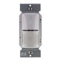
COVERAGE PATTERN
Do not obstruct the lens. NOTE: Plus 10° above horizon.
40 ft 35 ft13 ft13 ft TOP VIEW
180°
30+’
(9.1m)
20’
(6.1m)
4 ft
SIDE VIEW
13 ft 40 ft
Major motion
Minor motion
Major motion
Minor motion
PIR
Coverage
Ultrasonic
Coverage
35 ft
40 ft
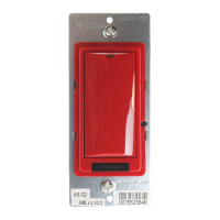
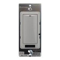
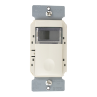
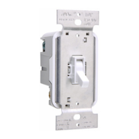
BUTTONS AND INDICATORS
Configuration Button
PIR Lens
PIR Detection LED (Red)
Ultrasonic Detectors
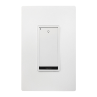
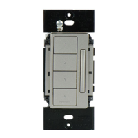
Button(s) can be set to
toggle on/off or to
function as a scene switch
Tap when load OFF: Tu
Tap when load ON: Go to full bright
Press & Hold: Ramp Up
Tap: Fade to OFF
Sensor Button
Ultrasonic Detection LED (Blue)
Status/Config LED
Status LED
MOUNTING
WARNING: Do Not Install To Cover a Junction Box Having
Class 1, 3 or Power and Lighting Circuits.