Wattstopper
®
DLM Wired Standar
d Switches
Quick Start Guide • Guide de démarrage rapide • Guía de inicio rápido
No: 31940 – 10/22 rev. 2
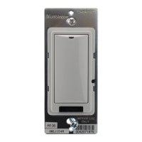
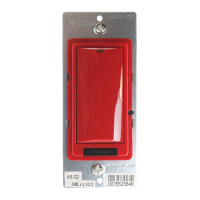
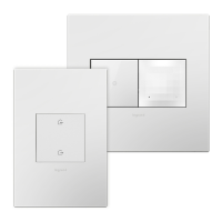
Catalog Numbers • Les Numéros de Catalogue • Los Números de Catálogo: LMSW-210, LMSW-211,
LMSW-220, LMSW-222, LMSW-241, LMSW-250
Country of Origin: Made in China • Pays d’origine: Fabriqué en Chine • País de origen: Hecho en China
This unit is pre-set for Plug n’ Go™ operation, adjustment is optional.
For full operational details, adjustment and more features of the product, see the
DLM System Installation Guide provided with Wattstopper room controllers, and
also available at www.legrand.us/wattstopper.
Installation shall be in accordance with all applicable regulations, local and
NEC codes. Wire connections shall be rated suitable for the wire size (lead and
building wiring) employed.
For Class 2 DLM devices and device wiring: To be connected to a Class 2 power
source only. Do not reclassify and install as Class 1, or Power and Lighting
Wiring.
Do not apply cleaning solvent directly onto unit. Apply cleaning solvent onto a
cloth, then wipe the unit to clean it.
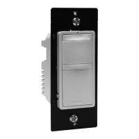
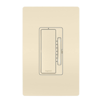
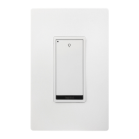
LMSW-220LMSW-211LMSW-210 LMSW-250LMSW-241LMSW-222
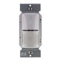
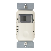
MOUNTING THE SWITCHBUTTONS AND INDICATORS
Status/
Config
LED
Tap when load OFF: Turn ON to last level
Tap when load ON: Go to full bright
Press & Hold: Ramp Up
Tap: Fade to OFF
Press & Hold: Ramp Down
Button(s) can be set
to toggle on/off or
to function as a
scene switch
Configuration Button
(Right side of Legrand badge/IR window)
LEDs show
light level
setting
(LMSW-211 only)
CAUTION: TO CONNECT A COMPUTER TO THE DLM LOCAL
NETWORK USE THE LMCI-100. NEVER CONNECT THE DLM
LOCAL NETWORK TO AN ETHERNET PORT – IT MAY
DAMAGE COMPUTERS AND OTHER CONNECTED EQUIPMENT.
WARNING: Do not install to cover a junction box having
Class 1, 3 or Power and Lighting Circuits.
SPECIFICATIONS
Voltage .............................................................................. 24VDC
Current Consumption .............................................................5mA
Power Supply ................................. Wattstopper Room Controller
Connection to the DLM Local Network .................... 2 RJ-45 ports
DLM Local Network characteristics when using LMRC-11x/2xx
room controllers:
Low voltage power provided over Cat 5e cable (LMRJ);
max current 800mA. Supports up to 64 load addresses,
48 communicating devices including up to 4 LMRC-10x
series and/or LMPL-101 controllers.
Free topology up to 1,000’ max.
Environment ................................................. For Indoor Use Only
Operating Temperature .................32° to 131°F (0° to 55°C)
Storage Temperature ...................23° to 176°F (-5° to 80°C)
Relative Humidity .......................5 to 95% (non condensing)
Patent Pending