Wattstopper
®
Digital Lighting Management Low Voltage Dimming Wall Switch (v3)
Gestion numérique de l’éclairage Interrupteur mural basse tension à gradation (v3)
Regulador de pared de bajo voltaje DLM (v3)
Quick Start Guide • Guide de démarrage rapide • Guía de inicio rápido
No: 23493 – 10/18 rev. 2
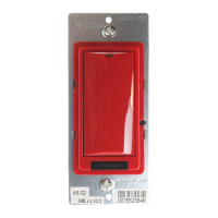
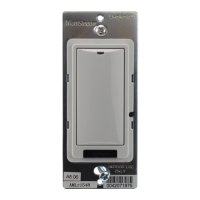
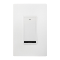
Catalog Number • Numéro de Catalogue • Número de Catálogo: LMDM-101
Country of Origin: Made in China • Pays d’origine: Fabriqué en Chine • País de origen: Hecho en China
Models ending in -U are BAA and TAA compliant (Product produced in the U.S.)
SPECIFICATIONS
Voltage ................................................................................... 24VDC
Current Consumption ..................................................................5mA
Power Supply ...................................... Wattstopper Room Controller
Connection to the DLM Local Network ......................... 2 RJ-45 ports
DLM Local Network characteristics when using LMRC-11x/2xx room
controllers:
Low voltage power provided over Cat 5e cable (LMRJ);
max current 800mA. Supports up to 64 load addresses,
48 communicating devices including up to 4 LMRC-10x
series and/or LMPL-101 controllers.
Free topology up to 1,000’ max.
Environment ...................................................... For Indoor Use Only
Operating Temperature ......................32° to 131°F (0° to 55°C)
Storage Temperature ........................23° to 176°F (-5° to 80°C)
Relative Humidity ............................5 to 95% (non condensing)
Patent Pending
MOUNTING THE SWITCH
WARNING: Do not install to cover a junction box having Class 1, 3 or
Power and Lighting Circuits.
This unit is pre-set for Plug n’ Go™ operation,
adjustment is optional.
For full operational details, adjustment and more
features of the product, see the DLM System Installation
Guide provided with Wattstopper room controllers, and
also available at www.legrand.us/wattstopper.
Installation shall be in accordance with all applicable
regulations, local and NEC codes. Wire connections
shall be rated suitable for the wire size (lead and building
wiring) employed.
For Class 2 DLM devices and device wiring: To be
connected to a Class 2 power source only. Do not
reclassify and install as Class 1, or Power and Lighting
Wiring.
Do not apply cleaning solvent directly onto unit. Apply
cleaning solvent onto a cloth, then wipe the unit to clean it..
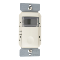
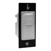
BUTTONS AND INDICATORS
Red LED
status LED
Tap when load OFF: Tu
Tap when load ON: Go to full bright
Press & Hold: Ramp Up
Configuration Button
(behind switch plate)
Tap: Fade to OFF
Press & Hold: Ramp Down
LEDs
show
light
level
setting
When all loads bound to the dimmer are OFF, the Blue load
status LED is dim. A single light level LED is lit to show the last
light level.
When any load bound to the dimmer is ON the load status
LED is bright. The number of illuminated light level LEDs
indicates the highest light level on any of those loads.
CONNECTIVITY
The illustrations here show examples of free-topology wiring. The LMDM communicate to all other Digital Lighting Management devices
connected to the low voltage DLM Local Network, regardless of their position on the DLM Local Network.
Line Voltage
Line Voltage
J-Box
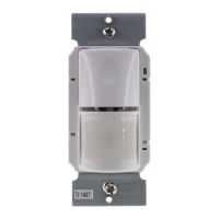
Occupancy Sensor
LMRC-212
Dimming
Room
Controller
Dimming Switch
LMDM-101
Dimming Switch
Scene Switch
Class 2 0-10 Volt Control Wiring
0-10 Volt
Ballast
0-10 Volt
Ballast
LMRJ Cables
Corner Mount
Occupancy
Sensor
Switch/
Ceiling Mount
Occupancy
Sensor
J Box
To
Load
DLM Local Network
LMRJ cables
LMRC-21x
Room
Controller
To 0-10V
Dimming Ballast
CAUTION: TO CONNECT A COMPUTER TO THE DLM LOCAL NETWORK USE THE LMCI-100. NEVER CONNECT THE DLM
LOCAL NETWORK TO AN ETHERNET PORT – IT MAY DAMAGE COMPUTERS AND OTHER CONNECTED EQUIPMENT.