8 X75 Quick Start Guide
X75SD/X75HD Multiple Path Converters and Frame Synchronizers Quick Start Guide
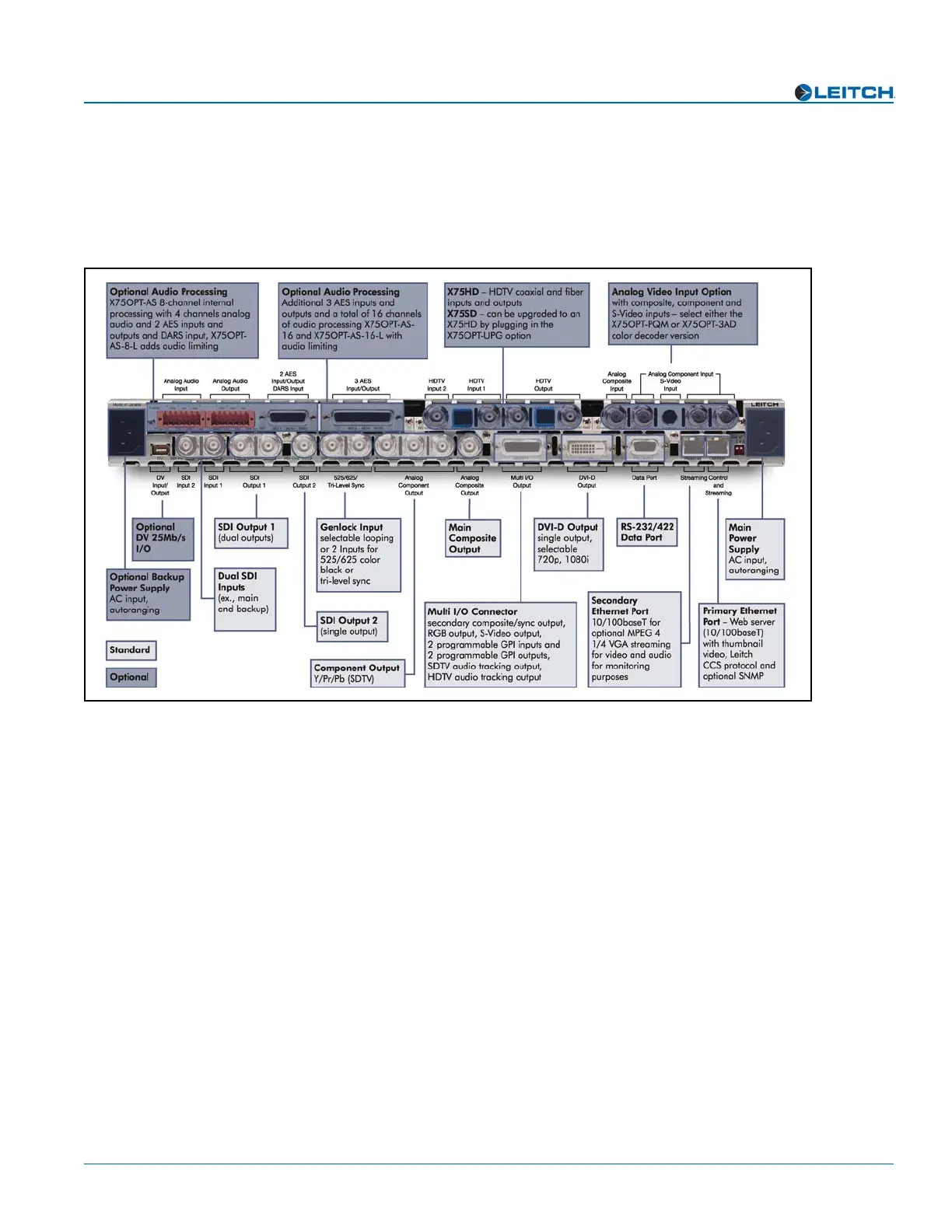
Making Cable and System Connections
Some connections to the X75 are provided via supplied breakout cable(s), others are
made directly to the frame via single-link cabling. Figure 7 identifies the various
connectors on the X75 back panel:
Figure 7. X75 Back Panel
When making cable connections, maintain approximately 10 in. (25 cm) of slack in the
rear connecting cables (wrap or tie extra cable around the cable relief bar). This allows
you to pull the frame out from the rack for servicing without needing to remove any
cable connections.
Descriptions of the various cable connections required can be found in Chapter 4:
“System Installation and Connections” of your X75SD/X75HD Multiple Path
Converters and Frame Synchronizers Installation and Operation Manual.