❏ ❏
❏ ❏
❏
22
22
2
BIAS ADJUSTEMENT
Instruments, materials and tools:Instruments, materials and tools:
Instruments, materials and tools:Instruments, materials and tools:
Instruments, materials and tools:
- Audio Generator
- Dual Trace Oscilloscope with 10x prober.
- Digital Voltmeter (or Multimeter)
- 8Ω 1000W Resistor
- Temperature Meter
Setup:Setup:
Setup:Setup:
Setup:
- Connect the Audio Generator to the input and set it to output 1KHz sinusoidal signal.
- Connect the Dual Trace Oscilloscope to the input (set CH1trace at 0.5V/div. 200usec./div) and to the output (set CH2 trace at 20V/div.
200usec/div) of the amplifier.
WARNING: The oscilloscope must be earth insulated.WARNING: The oscilloscope must be earth insulated.
WARNING: The oscilloscope must be earth insulated.WARNING: The oscilloscope must be earth insulated.
WARNING: The oscilloscope must be earth insulated.
- Insert the temperature sensor through the interstize between the heatsink and R15 (PTC).
- Unconnect amplifier's output from the cross-over and connect the 8Ω 1000W resistor instead of it.
- Insert the voltmeter terminals across R22.
ADJUSTMENT PROCEDUREADJUSTMENT PROCEDURE
ADJUSTMENT PROCEDUREADJUSTMENT PROCEDURE
ADJUSTMENT PROCEDURE
1) Turn on the amplifier.
2) Set the input signal to obtain approximatelly 120Vpp on the output.
3) When the temperature has reaches about 50°C (122°F) set the input level to minimum
4) Adjust the trimmer VR1 to read a voltage of 3±0.05mV on the multimeter.
5) Check that the voltage across the R74 resistor has the same value.
6) At the same temperature condition, adjust the VR2 trimmer to read 4±0.05mV across R26 resistor.
7) Check that the voltage on the R78 resistor has the same value.
Verifing:Verifing:
Verifing:Verifing:
Verifing:
1) Increase the input level to obtain an output voltage about of 0.5Vpp.
2) Check with the oscilloscope that the output signal is without a cross-talk distortion and eventually slightly adjust the VR1 position until
distortion disappears.
(Note: the voltage value across the R22 and across R74 resistor must not exceed 5mV)
3) Re-connect the cooling fan and the crossover instead of the 8Ω 1000W resistor.
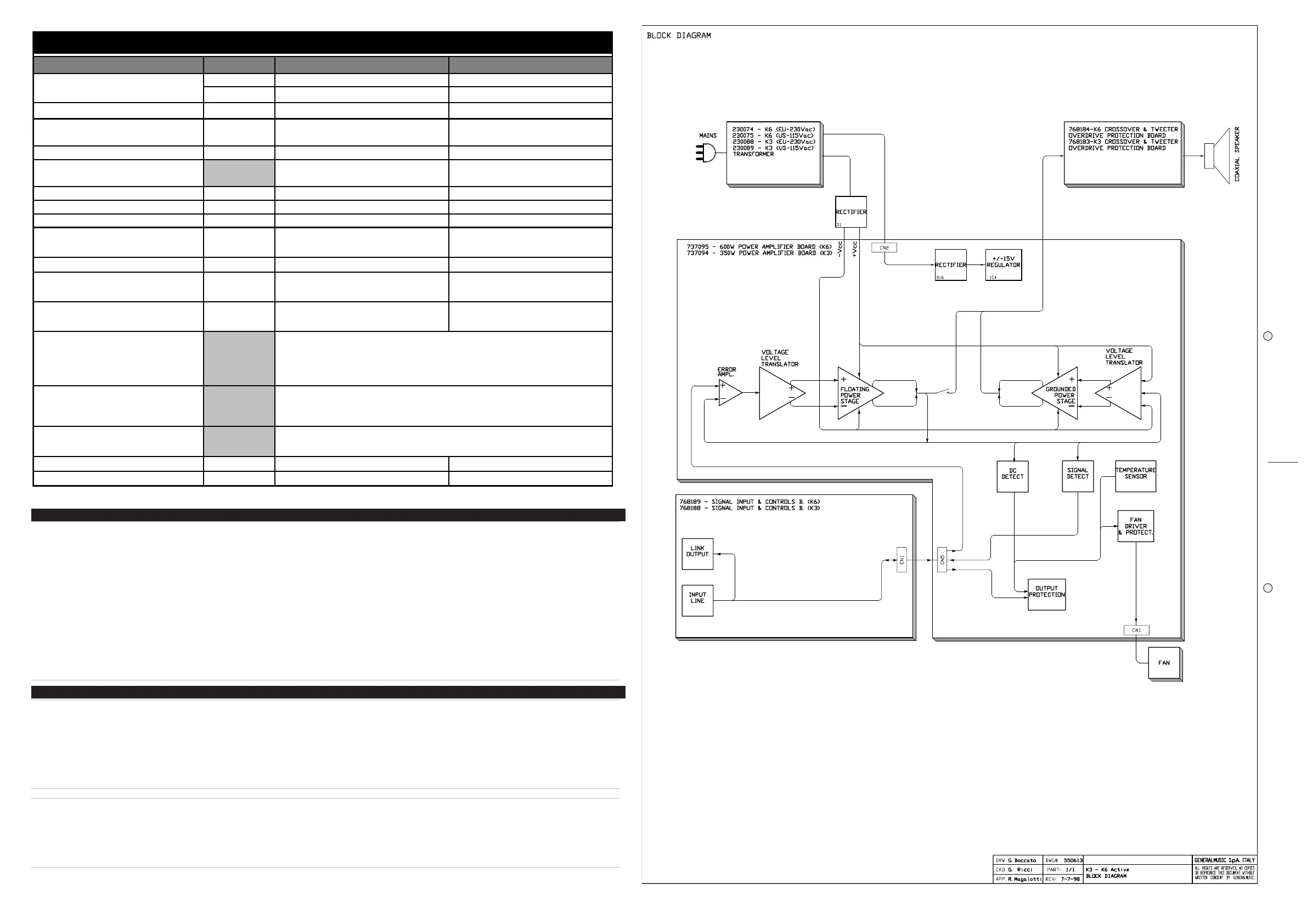
TECHNICAL SPECIFICATIONS
K 3 Active K 6 Active
POWER (EIA RS-426A)
Watts EIA 300 550
HANDLING
Watts IHF 350 600
DISTORTION
(THD+N) <0,02% <0,02%
INPUT
kohms 30 balanced 31 balanced
IMPEDANCE
kohms 15 unbalanced 15 unbalanced
INPUT SENSITIVITY
dB 0
0,775 V
0
0,775 V
230Vac +/-15% 50-60Hz
115Vac +/-15% 50-60Hz
230Vac +/-15% 50-60Hz
115Vac +/-15% 50-60Hz
SENSITIVITY
SPL 1W/1m
dB 100 100
MAX SPL
continous dB 121 124
MAX SPL
peak dB 124 127
FREQUENCY RESPONSE
Hz (-10dB) 60-20000 50-20000
DISPERSION ANGLE
(OxV) ° 60x60 60x60
CROSSOVER FREQUENCY
Hz 1,8kHz at 12-18dB/oct. 1,4kHz at 12-18dB/oct.
COMPONENTS
HIGH
LOW
1" driver coaxial
12" woofer
1.5" driver coaxial
15" woofer
Cabinet: birch pol
wood.
CONSTRUCTION
Finish: Black scratch-resistant paint
Metal Grille
Pol
urethane front panel
Volume Control.
CONTROLS
SHIELD
Limiter ON/OFF.
CONNECTIONS
Combo - 1 XLR-M
POWERCON power connector
DIMENSION
mm (WxHxD) 542x496x537 542x656x537
WEIGHT
kg 36 47