2
PROCON400p - Test procedures
PRECAUTION
• To prevent short circuit during any test, the oscilloscope must be
EARTH INSULATED, this occurs because some test require to connect
its probe to the amplifi er output, non-compliance may cause damages
to oscilloscope inputs circuitry.
• Before removing or installing any modules and connectors, disconnect
the amplifi er from AC MAINS and measure the DC supply voltages across
each of the power supply capacitors. If your measurement on any of
the caps is greater than 10Vdc, connect a 100E 60W resistor across
the applicable caps to discharge them for your safety. Remember to
remove the discharge resistor immediately after discharging caps. Do
not power up the amplifi er with the discharge resistor connected.
• Do not check the amplifi er with the speakers connected use the
appropriate load resistors only.
• BE CAREFUL increasing the Variac you must not exceed the nominal
mains voltage plus its tolerance (see specifi cations) any upper volt-
age can be cause of damage.
VISUAL CHECK
• Use compressed air to clear dust in the amplifi er chassis.
• Before proceed to supply the amplifi er check visually the internal
assembly, if appears an evident damage fi nd the most possible rea-
sons that cause it.
• Check the wiring cables for possible interruptions or shorts.
• If the damage has burnt a printed circuit board don’t try to repair
it, replace with a new one.
TESTING GEAR
• Audio Generator
• Dual Trace Oscilloscope
• Digital Multimeter
• 4E 300W, 8E 450W, 100E 60W resistors
• Variac
• Digital Thermometer (not indispensable)
SETUP
• Connect the Variac between the Mains and the amplifi er and set
it at zero voltage.
• Turn full counter-clockwise the LEVEL potentiometers.
• Connect the audio generator to the channel inputs and set it to
1KHz 775mVrms (0dBu) sinusoidal signal.
• Connect the two scope traces to the amplifi er outputs, before the
relay, and set them in DC at 20V/div. 2mS/div.
SUPPLY CHECK
• Verify with the Multimeter the insulation between the heatsinks and
all transistor collectors mounted on them; placing the multimeter tips
between the screw heads and the collector pins you can exclude an
erroneus reading due to the insulation of the heatsink anodization.
• Verify with the Multimeter the NTC (RT1) and R1 paralleled resistor
value, it must be about 1080ohm (at 25°c).
• Disconnect the amplifi er module supplies of each channel (red and
yellow wires).
• Set the Variac to the nominal mains voltage, turn on the Amplifi er,
then check with the Multimeter the AC supply voltages:
F1-F2 = 29±2Vac.
RED secondary wires = 87±9Vac.
• Re-set the Variac at zero voltage, turn off the amplifi er and recon-
nect the supplies at each amplifi er module.
• Set up the Variac slowly monitoring the oscilloscope screen, it should
display no signal; if you notice a DC voltage or a protection trips check
the amplifi er as suggested in the ADVICES.
• As soon as the +12VF supply circuit reaches its nominal value,
all cooling fans run at their minimum and the speaker output relais
(J201-202) switch.
• When the Variac ac voltage reaches the nominal voltage verify the
DC supplies as follow:
+VCC = +59±6Vdc
-VCC = -59±6Vdc
U101 pin 8 = +12±0.5Vdc
U101 pin 4 = -12±0.5Vdc
U403 pin 3 = +12±0.5Vdc
• If one or more voltages don’t correspond, check the rectifi ers, ca-
pacitors and transformers disconnecting them from cir cuit ry.
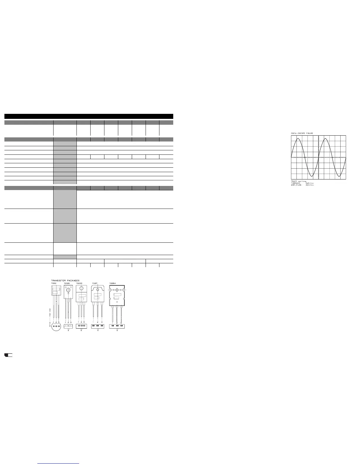
CHANNEL CHECK
• Be sure you have dis con nect ed the load re sis tor.
• Increasing the input sig nal also the output signal raise ac cord ing ly,
it must be sym met -
ri cal without vis i ble
dis tor tion or os cil la tion
as shown in figure
(note: the fi g ure is
rep re sent a tive don`t
re fer to the levels
dis played). If there is
a dis tor tion read the
sec tion ADVICES.
• When the input sig-
nal exceeds -20dBu
(20Vpp on output)
the fans turn at their
max i mum speed.
• Firstly you must
check the channel
without load, after-
wards you must repeat
the check with the loads attached, the following table reports the
approx. maximum level obtainable with this amp:
out level in level
no load 113Vpp +1.5dBu
1CH 4E 91Vpp -0.2dBu
2CH 4E 82Vpp -2.0dBu
Bridge 8E 161Vpp -2.3dBu
LEVEL METER ADJUSTMENT
• Check if the clip led lights at -2dBu on input (~80Vpp on output), if
necessary adjust the trimmers W301/2 on dis play board.
OFFSET ADJUSTMENT
• Set the input level at minimum (no signal), the output dc offset
voltage must be within range ±20mV, if necessary adjust the VR201
trimmer (for each channel) to be within this range.
BIAS ADJUSTMENT
• No bias adjustment is necessary for this amplifi er circuitry.
ADVICES
• If you have determinate that the problem is a short on a rail, you
must check the output transistors.
• To determine which transistor devices are bad, use a soldering iron
to lift one leg of each emitter pin and measure the resistance across
emitter and collector of each device. Unsolder and lift one leg of each
base pin and check the base-collector resistance. Replace any device
that measure as a short.
• If all the transistors are OK, unsolder and lift one leg of each diode
and check them.
• Check the circuit board for open foil traces.
• Use the Multimeter to check the resistors, particularly the base and
emitter resistors of damaged transistor.
• If the input sinewave appears to be distorted during the negative
cycle, you can assume that the problem is located somewhere in the
circuitry of the positive rail.
• If the positive cycle appears distorted, you can assume that the
problem is in the circuitry of the negative rail.
• The dc voltages printed on the schematics are measured with the
amplifi er in steady state without input signal and nominal mains volt-
age supply, it can be useful to localize a damage.
POWER SPECIFICATIONS
400P 750P 1000P 1250P 1500P 1800P 2200P
EIA output power
1kHz, THD maximum 1%
Both channels
8 ohm
4 ohm
8 ohm BRIDGED
125+125
200+200
400
215+215
375+375
750
300+300
550+550
1100
375+375
625+625
1250
450+450
750+750
1500
550+550
900+900
1800
650+650
1100+1100
2200
ELECTRICAL SPECIFICATIONS
400P 750P 1000P 1250P 1500P 1800P 2200P
INPUT SENSITIVITY
INPUT IMPEDANCE
FREQUENCY RESPONSE
VOLTAGE GAIN
32dB 33dB 35dB 36dB 37dB 37dB 39dB
SLEW RATE
DAMPING FACTOR
CROSSTALK
S/N ratio
Harmonic distortion THD
Intermodulation distortion SMPTE
GENERAL SPECIFICATIONS
400P 750P 1000P 1250P 1500P 1800P 2200P
PROTECTIONS
CONTROLS
INDICATORS
CONNECTORS
IN
OUT
POWER SUPPLY
DIMENSIONS
mm (WxHxD)
WEIGHT
kg 13 15 18 19.5 21 23.5 25
PROCON PLUS SERIES • TECHNICAL SPECIFICATIONS
0dB (0.775V)
10 kOhms (balanced)
10÷50000 Hz (-0.5dB)
22 V/ms
>400:1 @ 1kHz, 8Ohms
-82 dB (1KHz)
Power transformer thermal protection
Short circuit protection
Sensor for current on outputs
CLIP Limiter on each channel
Soft-start circuit (1000P to 2200P)
-100 dB
483x88x456
<0.1% (ref 20Hz -20KHz)
<0.1% (SMPTE method, 60Hz & 7kHz, 4:1 ratio)
1 XLR-F + 1 JACK in parallel for each channel
2 x BINDING POST + 1 SPEAKON for each channel (400-1500)
1 SPEAKON for each channel + 1 SPEAKON for BRIDGE output (1800-2200)
483x88x366 483x88x428
ON/OFF switch
21-detect input level control for each channel
MODE selector
SHIELD selector
POWER ON: 1 red LED
BRIDGE: 1 red LED
PROTECT: 1 red LED
LEVEL: 2 x 5-LED meters
LIMIT: 1 red LED
see label on the unit
 Loading...