procon plus
7
NB: Whenever possible, use balanced cables. In any case, avoid
using a balanced cable for one channel and an unbalanced one
for the other, as this would cause a considerable difference in
channel levels.
2. LINK
Balanced JACK connectors (0 dB).
These connectors are connected in parallel with the
respective XLR-F connectors. This enables a second
unit (e.g. another amplifi er) to be daisy-chained to the
fi rst. It’s thus possible to feed several amplifi ers using
the same signal.
3. OUTPUTS
Power connectors.
In the 400P, 750P, 1000P, 1250P and 1500P models
each channel has 1 SPEAKON and 2 BINDING POST
connectors wired in this way:
- PIN 1+ connected in parallel to the “+” BINDING POST
“+” (red color);
- PIN 1- connected in parallel to the “-” BINDING POST
“+” (black color);
- PIN 2+ and 2- NOT connected.
The BRIDGE output is made up of the two positive
BINDING POST connectors (red color) and its polarity
is printed on the amplifi er's panel.
In the 1800P and 1500P models each channel has just
1 SPEAKON and the BRIDGE output is made up of
another dedicated SPEAKON connector.
NOTE: to avoid possible damage to the loudspeaker enclosures,
only connect enclosures or speaker systems compatible with
the power load and impedance limits indicated for the amplifi er
(regarding this, consult the “Technical specifi cations” chapter for
reference to your specifi c amplifi er model). Use only loudspeaker
enclosure cables, never signal cables, i.e. those normally used for
microphones, instruments and audio equipment in general.
4. MODE
Selector for the amplifi er's two operating modes.
a) STEREO: in this operating mode 2 separate signals
are treated separately by channels 1 and 2 of the
amplifi er and sent respectively to outputs 1 and 2.
b) BRIDGE: in this operating mode 1 single signal
connected to the input 1 is amplifi ed by the two sections
of the amplifier summed together and sent to the
BRIDGE output with double the power and rated
impedance (see Technical Specifi cations).
In the 400P, 750P, 1000P, 1250P and 1500P models
the BRIDGE output is made up of the two positive
BINDING POST connectors (red color) and its polarity
is printed on the amplifi er's panel.
In the 1800P and 1500P models the BRIDGE output
has its own dedicated SPEAKON connector.
In the event of breakdown, contact the nearest
GENERALMUSIC Assistance Centre.
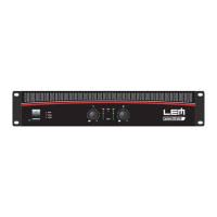
4. Functions & Controls (fi g. 1)
1. POWER ON/OFF
ON/OFF switch.
2. POWER ON LED
LED indicating when the amplifi er is switched on.
3. BRIDGE LED
LED indicating when the BRIDGE mode is activated
(see MODE in Connection Panel).
4. INPUT ATTENUATORS
Input gain attenuator potentiometers.
Attenuate the level of the external signal sent to the
respective channels of the amplifi er.
Continuously variable values, expressed in dB, are
between:
∞
: fully closed (the signal is completely attenuated
and therefore not sent to the channel of the
amplifi er);
0 : fully open, i.e. nominal level (the signal is not
attenuated in any way, so is fed to the amplifi er
channel at the same level at which it arrives on
input).
5. METERS
5-LED bargraphs for the visualization of the input
signal. The LEDs are of three different colors:
• green: show the normal operative level of the
signal;
• yellow: light up at -6dB referred to the maximum
level;
• red (CLIP): indicate clipping (the audio signal level
exceeds the output capacity of the
amplifi er channel). When these LEDs
fl ash reduce the input signal level.
6. LIMIT LED
CLIP LIMITER indicator.
Indicates that the CLIP LIMITER circuit has sensed a
too high input signal and has therefore activated the
LIMITER in order to avoid excessive distortions.
5. Connection Panel (fi g. 2)
1. INPUTS
Balanced XLR-F connectors (0 dB).
The inputs of the amplifi er’s two channels. Can receive
balanced or unbalanced high impedance line signals
from equipment with high level outputs.