8
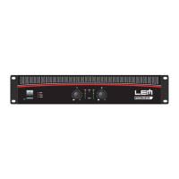
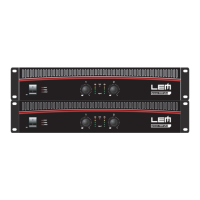
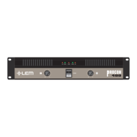
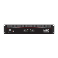
procon plus
You can fi nd schematic drawings for each operating
mode in the CONNECTION EXAMPLES section.
5. SHIELD
Control for separating the electrical earth from that
of the chassis. Use this control to try to eliminate hum
noises due to so-called 'ground loops'.
6. A.C. ~
Power cord.
7. Main fuse holder
In the event of breaking, always replace the fuse with
same type and rating.
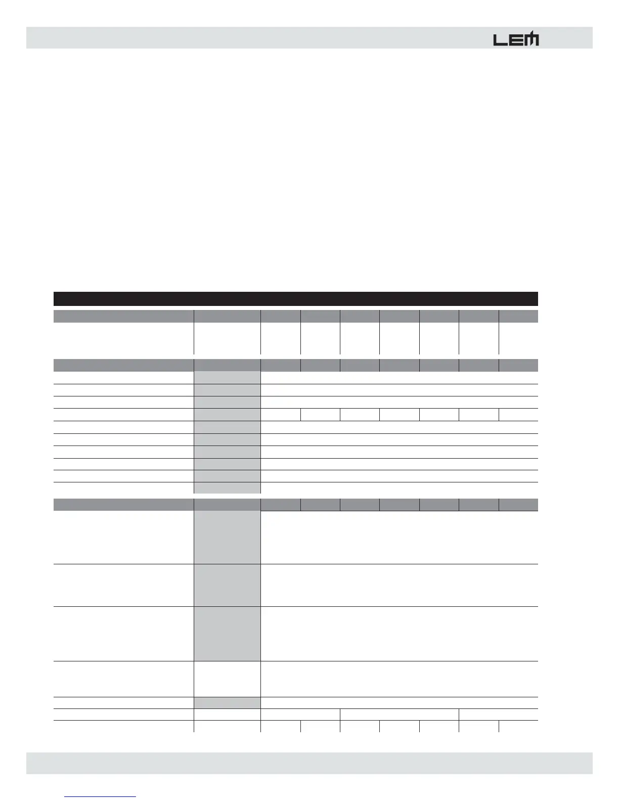
POWER SPECIFICATIONS
400P 750P 1000P 1250P 1500P 1800P 2200P
EIA output power
1kHz, THD maximum 1%
Both channels
8 ohm
4 ohm
8 ohm BRIDGED
125+125
200+200
400
215+215
375+375
750
300+300
550+550
1100
375+375
625+625
1250
450+450
750+750
1500
550+550
900+900
1800
650+650
1100+1100
2200
ELECTRICAL SPECIFICATIONS
400P 750P 1000P 1250P 1500P 1800P 2200P
INPUT SENSITIVITY
INPUT IMPEDANCE
FREQUENCY RESPONSE
VOLTAGE GAIN
32dB 33dB 35dB 36dB 37dB 37dB 39dB
SLEW RATE
DAMPING FACTOR
CROSSTALK
S/N ratio
Harmonic distortion THD
Intermodulation distortion SMPTE
GENERAL SPECIFICATIONS
400P 750P 1000P 1250P 1500P 1800P 2200P
PROTECTIONS
CONTROLS
INDICATORS
CONNECTORS
IN
OUT
POWER SUPPLY
DIMENSIONS
mm (WxHxD)
WEIGHT
kg 13 15 18 19.5 21 23.5 25
483x88x456
<0.1% (ref 20Hz -20KHz)
<0.1% (SMPTE method, 60Hz & 7kHz, 4:1 ratio)
1 XLR-F + 1 JACK in parallel for each channel
2 x BINDING POST + 1 SPEAKON for each channel (400-1500)
1 SPEAKON for each channel + 1 SPEAKON for BRIDGE output (1800-2200)
483x88x366 483x88x428
ON/OFF switch
21-detect input level control for each channel
MODE selector
SHIELD selector
POWER ON: 1 red LED
BRIDGE: 1 red LED
PROTECT: 1 red LED
LEVEL: 2 x 5-LED meters
LIMIT: 1 red LED
see label on the unit
22 V/ms
>400:1 @ 1kHz, 8Ohms
-82 dB (1KHz)
Power transformer thermal protection
Short circuit protection
Sensor for current on outputs
CLIP Limiter on each channel
Soft-start circuit (1000P to 2200P)
-100 dB
PROCON PLUS SERIES • TECHNICAL SPECIFICATIONS
0dB (0.775V)
10 kOhms (balanced)
10÷50000 Hz (-0.5dB)