Do you have a question about the Lennox 13ACX?036 and is the answer not in the manual?
| Brand | Lennox |
|---|---|
| Model | 13ACX?036 |
| Category | Air Conditioner |
| Language | English |
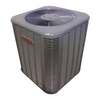
13ACX condensing units are available in 1-1/2 to 5 ton capacities for residential applications.
Explains the control box, lack of indoor transformer, and 24 VAC control power from indoor unit.
Details electrostatic discharge precautions for protecting electronic controls during installation and service.
Describes the single-pole contactor that energizes the compressor via thermostat Y1 signal.
Identifies the dual capacitor used for both fan and compressor motors in permanent split capacitor units.
Explains the time delay function electrically connected between thermostat Y and compressor contactor.
Details the simple, efficient design of the scroll compressor with few moving parts.
Illustrates the scroll form and cross-section showing how gas is compressed by orbital motion.
Describes single-phase PSC fan motors and how to access them by removing screws.
Explains the auto-reset switch that shuts off the compressor when suction pressure drops below a set point.
Details the manually reset switch that stops the compressor when discharge pressure exceeds a set point.
Covers liquid and suction line requirements and Lennox L15 line set compatibility.
Illustrates service valves, gauge ports, and procedures for leak testing and operation.
Details the ball valve construction and operation specific to 5-ton units.
Procedure for leak testing the system using nitrogen pressurization after line set connection.
Guidance on using an electronic leak detector to find leaks in the refrigerant system.
Explains why evacuating noncondensables is crucial for unit operation and longevity.
Steps for evacuating the system using a vacuum pump and micron gauge to achieve deep vacuum.
Describes how to check indoor airflow using wet-bulb and dry-bulb temperatures before charging.
Table 2 provides expected liquid and vapor pressures for TXV systems at various outdoor temperatures.
Table 2 provides expected liquid and vapor pressures for RFC systems at various outdoor temperatures.
A flowchart to guide selection between Weigh-in, Approach, Subcooling, or Superheat methods.
Instructions for weighing in the correct refrigerant charge, including line set length adjustments.
Table 3 specifies how to adjust refrigerant charge based on liquid line diameter and length.
Detailed procedure for calculating superheat to ensure proper charge in RFC systems.
Table 4 lists HFC-410A pressures corresponding to saturation temperatures for charging.
Detailed procedure for calculating approach temperature to ensure proper charge in TXV systems.
Detailed procedure for calculating subcooling to ensure proper charge in TXV systems.
Guidance on restricting outdoor coil airflow to achieve necessary pressures for subcooling checks.
Step-by-step instructions for cleaning the outdoor coil, including mesh screen access.
Covers cleaning indoor coils, checking connections, condensate pan, and filters.
Provides the electrical wiring diagram for the 13ACX unit, detailing component connections.
Explains the sequence of events during the cooling mode, from thermostat call to compressor/fan operation.