conditionhasbeencorrected.Contactyourdealerifyou
desiremoreinformationaboutthisimportantsafetyfeature.
Shouldanyunusualconditionsbeobservedduringyour
inspections,callanauthorizedservicedealerimmediately.
Return Air
All return air duct connections must be tight and sealed to
unit cabinet. Supply and return air registers must be open
when the unit is in operation. Obstructions must not be
allowed to block airflow in or out of the registers.
Filters
Air filters are to be used with this heating/cooling unit.
Filters are not factory supplied in the unit. However, a filter
frame accessory is available from the manufacturer that
allows filters to be installed within the unit. [f the filter
frame accessory is not used, a filter must be installed in
the duct work by the installer. Filters must always be
installed ahead of the evaporator coil and must be kept
clean or replaced. Dirty filters will reduce the airflow of the
unit. Filters should be sized in accordance with Table 1.
Minimum Required Surface Area
for Disposable Filters
24,000 2.67
36,000 4.00
I
421000 I 4.67
48,000 5.33
60,000 I 6.67
Table 1
Outdoor Coil
Leaves and other large obstructions should be carefully
removed from the outdoor coil surfaces without damaging
the fin surface of the coil.
Lubrication
Lubrication of the bearings in the circulating air blower motor
and the combustion blower motor is not recommended.
Blower Assembly
Even with good filters properly in place, blower wheels
and motors will become dust laden after long months of
operation. The entire blower assembly should be in-
spected annually. If the motor and wheel are heavily
coated with dust, they can be brushed and cleaned with a
vacuum cleaner.
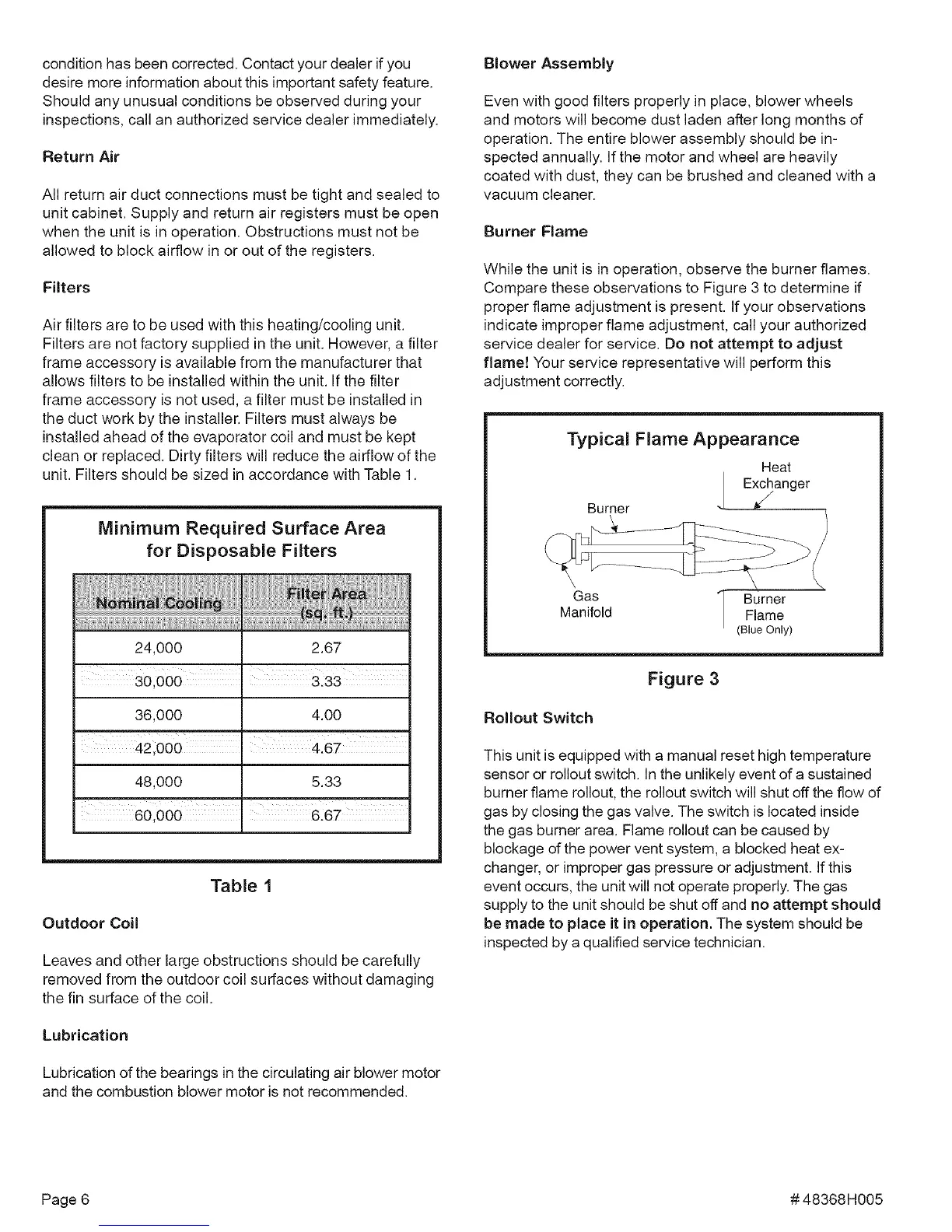
Burner Flame
While the unit is in operation, observe the burner flames.
Compare these observations to Figure 3 to determine if
proper flame adjustment is present. If your observations
indicate improper flame adjustment, call your authorized
service dealer for service. Do not attempt to adjust
flam!! Your service representative will perform this
adjustment correctly.
Typical Flame Appearance
Heat
Exchanger
Burner _¢/
Gas Burner
Manifold Flame
(Blue Only)
Figure 3
Rollout Switch
This unit is equipped with a manual reset high temperature
sensor or rollout switch. In the unlikely event of a sustained
burner flame rollout, the rollout switch will shut off the flow of
gas by closing the gas valve. The switch is located inside
the gas burner area. Flame rollout can be caused by
blockage of the power vent system, a blocked heat ex-
changer, or improper gas pressure or adjustment. If this
event occurs, the unit will not operate properly. The gas
supply to the unit should be shut off and no attempt should
be made to place it in operation. The system should be
inspected by a qualified service technician.
Page 6 #48368H005
 Loading...