INSTALLAT I STRUCTIO
Gas
(2,4)PG E/SG(13/15)
Heatin ectric Coolin
Series
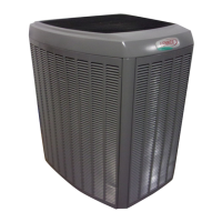
Package Unit
TABLE OF CONTENTS
SAFETY ................................................. 2
INSTALLATION ....................................... 2
START-UP ............................................ 10
OPERATION ........................................ 11
MAINTENANCE ................................... 13
CONTROL SYSTEM DIAGNOSTICS .. 14
WIRING DIAGRAMS ............................ 15
Manufactured By
A.A.C.
A Lennox International Inc. Company
421 Monroe Street
Bellevue, OH 44811
6AS-HREB
II!il!iilIIIllUI!11II o
I A CAUTION1
The installation of the furnace, wiring, warm air ducts, venting, etc. must conform to the requirements of the
National Fire Protection Association; the National Fuel Gas Code, ANSI Z223.1 (latest edition) and the
National Electrical Code, ANSl/NFPA No. 70 (latest edition) in the United States; the Canadian Installation
Codes CAN/CGA-B149.1 & .2 (latest edition) and the Canadian Electrical Code Part 1, CSA 22.1 (latest
edition) in Canada; and any state or provincial laws, local ordinances, or local gas utility requirements. Local
authorities having jurisdiction should be consulted before installation is made. Such applicable regulations
or requirements take precedence over the general instructions in this manual.
# 48111B005 Save these instructionsfor future reference Page 1