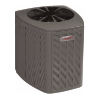
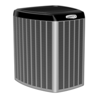
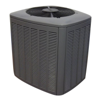
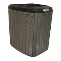
Do you have a question about the Lennox XC20-036-230-01 and is the answer not in the manual?
| Cooling Capacity | 36, 000 BTU/h |
|---|---|
| SEER | 20 |
| Refrigerant | R-410A |
| Voltage | 230V |
| Phase | 1 |
| Frequency | 60 Hz |
| Sound Level | 65 dB |
Identifies the different components of the unit's model number for recognition.
Explains the structure and meaning of the unit's serial number for tracking.
Lists key technical data such as sound rating, charge, and fan details.
Provides detailed electrical specifications for safe installation and operation.
Shows physical dimensions and mounting hole patterns for installation planning.
Illustrates the layout of major components within the control panel for identification.
Diagrams showing the location of key plumbing components like the compressor and drier.
Explains the function and operation of the unit's service valves for refrigerant handling.
Provides general installation guidelines and system overview information.
Detailed instructions on operating angle-type and ball-type service valves.
Guidelines for positioning the unit, including clearance and site selection.
Instructions for using stabilizers to secure the unit on uneven surfaces.
Considerations for mounting the unit on a roof structure.
Details on unit placement, slab mounting, and stabilizing on uneven surfaces.
Step-by-step guide for safely removing and reinstalling unit panels.
Information and recommendations for installing new or replacement refrigerant line sets.
Guidelines for sizing refrigerant line sets for HFC-410A cooling systems.
Specifies requirements for installing suction traps in certain system configurations.
Illustrates proper methods for isolating refrigerant lines to prevent vibration.
Provides procedures and safety precautions for brazing refrigerant line set connections.
Steps for preparing the piping panel and line set for brazing.
Instructions for removing service port caps and cores.
Guide on connecting manifold gauges for brazing operations.
Procedure for protecting service valves during brazing with water-saturated cloths.
Instructions for flowing nitrogen through the system during brazing.
Details on the brazing process, including protecting components.
Procedures for flushing the line set and indoor coil, especially for HCFC-22 conversions.
Steps for installing a new check expansion valve in the system.
Instructions for correctly installing the sensing bulb.
Steps for installing the equalizer line connection.
Procedures and important notes for leak testing the refrigeration system.
Instructions for connecting the manifold gauge set for leak testing.
Detailed procedure for performing a system leak test.
Steps for connecting gauges and vacuum pump for system evacuation.
Procedures for evacuating the system to the required vacuum level.
General electrical wiring requirements and codes.
Information on the 24VAC transformer used for low-voltage control.
Guidance on sizing circuits and installing disconnect switches.
Recommendations for thermostat installation location and height.
Instructions for routing low-voltage control wiring.
Guidance on routing high-voltage wiring and ground connections.
Precautions to prevent damage to electronic components from static discharge.
Table detailing the function of each terminal on the outdoor control board.
Further details on outdoor control terminal designations and input/outputs.
Procedures for starting up the unit after servicing or installation.
Explanation of alert and status codes displayed on the 7-segment display.
Lists alert codes and their possible causes and clearing methods.
Lists alert codes and their possible causes and clearing methods.
Lists alert codes and their possible causes and clearing methods.
Lists alert codes and their possible causes and clearing methods.
Lists alert codes and their possible causes and clearing methods.
Explains the power-up sequence and status displays on the 7-segment display.
Describes the idle mode status display and its meaning.
Details on using the 7-segment display for testing fan operation.
Procedure for recalling stored error codes from the control.
Overview of the field test mode for diagnostics.
Explains how to access and use the diagnostic mode.
Describes the operation of the outdoor fan in diagnostic mode.
Instructions for operating the unit in pump-down mode.
Guide to using the push-button for accessing modes like diagnostic and error recall.
Explains how to set the unit selection code for proper configuration.
Example of the 7-segment display during operation, showing various parameters.
Procedure to enable display of liquid line and coil temperatures on the 7-segment display.
Steps to manually assign the unit selection code for system configuration.
Refers to thermostat installer setup guide for configuration procedures.
Explanation of the compressor protection feature and lockout mechanism.
Lists diagnostic information available via the thermostat.
Maintenance checklist for the outdoor unit, including cleaning and checks.
Specific maintenance advice for the outdoor coil, including flushing.
Maintenance checklist for the indoor unit.
Specific maintenance advice for the indoor coil.
Recommendations for units in areas prone to snow or freezing rain.
Wiring diagram for specific XC20 models.
Wiring diagram for specific XC20 models.
Specific wiring detail for load shedding feature.
Detailed factory wiring diagram for specific unit models.
Detailed factory wiring diagram for specific unit models.
Flowchart describing the unit's startup sequence and operation.
Flowchart detailing the operation sequence of the low-pressure switch.
Flowchart detailing the operation sequence of the high-pressure switch.
Procedures for testing the high and low pressure switches.
Lists alert codes related to high and low pressure switches and their causes.
Details on compressor operation, testing, and related error codes.
Explains status codes displayed for compressor operation.
Lists compressor-related error codes and their remedies.
Lists compressor-related error codes and their remedies.
Information about the crankcase heater operation.
Details on the thermostat controlling the crankcase heater.
Describes the function and features of the compressor sound cover.
Explains the purpose and specifications of the liquid line filter drier.
Details on the operation and testing of the top cap thermal switch.
Lists alert codes related to the top cap switch.
Explanation of reactor operation, testing, and error codes.
Procedure for checking VAC voltage to the outdoor fan motor.
Procedure for checking VDC output from the control to the fan motor.
Notes on status/error codes related to the outdoor fan motor.
Explanation of ferrites and their purpose in controlling RF interference.
Lists status codes for the outdoor control.
Lists error codes related to the outdoor control and their causes/clearing.
Details component sensor operations, testing, and error codes.
Details about the absence of a sensor and the use of a resistor for continuity.
Information about the ambient temperature sensor and fault conditions.
Information about the liquid line temperature sensor and fault conditions.
Instructions for checking sensor operation by reading resistance.
Details inverter components, operation, checkout, status, and error codes.
Describes the operation of EMC, Converter, PFC, IPM, and Communication circuits.
Lists status codes for the inverter.
Lists error codes related to the inverter.
Important notes regarding system refrigerant and charging procedures.
Guidance on adding or removing HFC-410A refrigerant.
Procedure for checking indoor airflow using Delta-T.
Diagram and instructions for connecting gauge sets for charging.
Chart and instructions for checking indoor airflow and adjusting fan speed.
Method for weighing in refrigerant based on line set length and diameter.
Method for verifying refrigerant charge using subcooling.
Tables providing charging data based on temperatures and pressures.





 Loading...