XC20 — HFC-410A CHARGING INFORMATION
FOR COMPLETE CHARGING DETAILS, REFER TO THE OUTDOOR UNIT INSTALLATION AND SERVICE PROCEDURE (CORP 1407-L10).
IMPORTANT !
Room thermostat must be turned down at least 5°F from set point so charging occurs with
system operating at 100% capacity. Seven-segment display on outdoor control will show
outdoor unit running capacity.
The unit is factory‐charged with the amount of HFC-410A refrigerant indicated on the unit rating
plate. This charge is based on a matching indoor coil and outdoor coil with 15 feet (4.6 m) line
set. The outdoor unit should be charged during warm weather. However, applications arise in
which charging must occur in the colder months. The method of charging is determined by the
outdoor ambient temperature. Before charging the unit, determine the liquid line temperature
and the outdoor ambient temperature.
Charge Using the Weigh-In Method — Outdoor Temperature < 64ºF (17.7ºC)
If the system is void of refrigerant, or if the outdoor ambient temperature is 64°F (17.7°C) and below,
the refrigerant charge should be weighed into the unit. Do this after any leaks have been repaired.
NOTE - See system Installation Instructions to calculate charge required for longer line sets.
1. Recover the refrigerant from the unit.
2. Conduct a leak check, then evacuate the system as shown in the installation instructions.
3. Weigh in the unit nameplate charge.
If weighing facilities are not available, or if you are charging the unit during warm weather,
follow one of the other procedures outlined below.
Charge Using The Subcooling Method — Outdoor Temperature > 65ºF (18.3ºC)
When the outdoor ambient temperature is
65ºF (18.3ºC) and above, use the
subcooling method to charge the unit. It
may be necessary to restrict the air flow
through the outdoor coil to achieve
pressures in the 325-375 psig (2240-2485
kPa) range. These higher pressures are
necessary for checking the charge. Block
equal sections of air intake panels and
move obstructions sideways until the liquid
pressure is in the 325-375 psig (2240-2485
kPa) range. See figure 1.
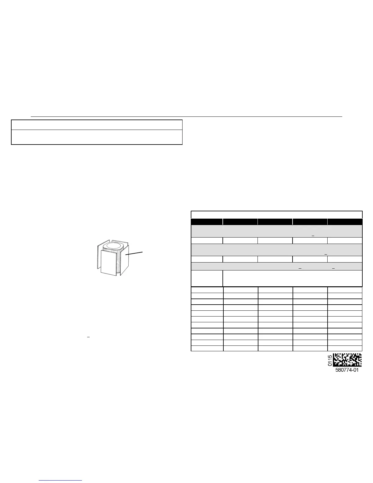
Block coil one side at a time with
cardboard/plastic until proper testing
pressures are reached.
Figure 1. Blocking Outdoor Coil
CARDBOARD
OR PLASTIC
SHEET
1. With the manifold gauge connected to the liquid line service port, allow the unit pressures
to stabilize, then, use a digital thermometer to record the liquid line temperature.
2. At the same time, record the liquid line pressure reading.
3. Use a temperature/pressure chart for HFC-410A to determine the saturation temperature
for the liquid line pressure reading.
4. Subtract the liquid line temperature from the saturation temperature (according to the
chart) to determine subcooling (Saturation temperature - Liquid line temperature =
Subcooling Value).
5. Compare the subcooling value with those in table 1. If subcooling is greater than shown,
recover some refrigerant. If subcooling is less than shown, add refrigerant.
Charge Using Normal Operating Pressures/Approach or Subcooling Methods
(High Capacity) —Outdoor Temperature >65ºF (18.3ºC)
When the outdoor ambient temperature is 65ºF (18.3ºC) and above, use the approach or
subcooling methods to charge the system. For best results, indoor temperature should be 70°F
(21°C) to 80°F (26°C). Monitor system pressures while charging.
1. Record outdoor ambient temperature using a digital thermometer.
2. Attach high pressure gauge set and operate unit for several minutes to allow system
pressures to stabilize.
3. Compare stabilized pressures with those provided in table 3, “Normal Operating
Pressures.” Minor variations are to be expected; significant differences could mean that
the system is not properly charged or that a problem exists with some component in the
system. Pressures higher than those listed indicate that the system is overcharged.
Pressures lower than those listed indicate that the system is undercharged. Verify adjusted
charge using the approach method.
4. Use the same digital thermometer used to check outdoor ambient temperature to check
liquid line temperature. Verify the unit charge using the approach method.
5. The difference between the liquid and ambient temperatures should match values given
in table 2. If the values don't agree with the those in table 2, add refrigerant to lower the
approach temperature or recover refrigerant from the system to increase the approach
temperature.
Using the Normal Operating Pressures Table
Table 3 may be used to help perform maintenance checks. This table is not a procedure for
charging the system and any minor variations in the pressures may be expected due to
differences in installations. However, significant deviations could mean that the system is not
properly charged or that a problem exists with some component in the system.
Charging Temperatures and Pressures – High Speed Only
XC20 Model -024 -036 -048 -060
Table 1 - Subcooling Values (High Capacity)
Saturation Temperature minus Liquid Line Temperature ºF (ºC) + 1ºF (0.5ºC)
Temp. °F (°C)
9 (5) 13 (7.2) 12 (6.7) 7 (3.9)
Table 2 - Approach Values (High Capacity)
Liquid Line Temperature minus Outdoor Ambient Temperature ºF (ºC) + 1ºF (0.5ºC)
Temp. °F (°C)
5 (2.8) 4 (2.2) 6 (3.3) 8 (4.4)
Table 3 - Normal Operating Pressures (Liquid +10 & Suction +5 psig)
Air
Temperature
Entering
Outside Coil
The values below are typical pressures; indoor evaporator match-up, in
door air quantity, and evaporator load will cause the pressures to vary.
Liquid Line Pressure / Vapor Line Pressure
65 (18.3) 235 / 139 247 / 141 247 / 137 238 / 133
70 (21.1) 252 / 140 262 / 142 267 / 139 255 / 134
75 (23.9) 272 / 141 284 / 143 288 / 139 274 / 135
80 (26.6) 293 / 142 304 / 144 310 / 140 295 / 136
85 (29.4) 316 / 144 327 / 145 332 / 142 316 / 137
90 (32.2) 340 / 144 350 / 146 358 / 143 338 / 138
95 (35.0) 364 / 145 375 / 147 383 / 143 362 / 139
100 (37.7) 390 / 146 400 / 148 410 / 144 388 / 141
105 (40.6) 417 / 147 426 / 149 437 / 145 415 / 142
110 (43.3) 445 / 149 457 / 150 467 / 146 442 / 143
115 (46.1) 474 / 150 487 / 150 497 / 148 470 / 144

 Loading...