Page 1
2010 Lennox Industries Inc.
Revised August 2, 2010
XC17
Service Literature
Corp. 1022−L3
XC17 (HFC−410A) SERIES UNITS
NOTICE
A thermostat is not included and must be ordered
separately.
D The Lennox icomfort Toucht thermostat must be used
in communicating applications.
D In non−communicating applications, the Lennox
ComfortSense
®
7000 thermostat may be used, as well
as other non−communicating thermostats.
In all cases, setup is critical to ensure proper system
operation.
Field wiring examples for non−communicating
applications begin on page 22.
See the icomfort Toucht thermostat Quick Start Guide
for communicating and partial communicating field wiring
connections.
WARNING
Improper installation, adjustment, alteration, service or
maintenance can cause personal injury, loss of life, or
damage to property.
Installation and service must be performed by a licensed
professional installer (or equivalent) or a service agency.
Accessories
For update−to−date information, see any of the following
publications:
S Lennox XC17 Engineering Handbook
S Lennox Product Catalog
S Lennox Price Book
TABLE OF CONTENTS
Model Number Identification 2. . . . . . . . . . . . . . . . . . . .
Typical Serial Number Identification 2. . . . . . . . . . . . . .
Specifications 2. . . . . . . . . . . . . . . . . . . . . . . . . . . . . . . . .
Electrical Data 3. . . . . . . . . . . . . . . . . . . . . . . . . . . . . . . .
Unit Dimensions 4. . . . . . . . . . . . . . . . . . . . . . . . . . . . . .
Typical Unit Parts Arrangement 5. . . . . . . . . . . . . . . . .
Operating Gauge Set and Service Valves 6. . . . . . . . .
Unit Placement 8. . . . . . . . . . . . . . . . . . . . . . . . . . . . . . .
Removing and Installing Panels 11. . . . . . . . . . . . . . . . .
New or Replacement Line Set 12. . . . . . . . . . . . . . . . . .
Flushing the System 15. . . . . . . . . . . . . . . . . . . . . . . . . . .
Leak Testing the System 17. . . . . . . . . . . . . . . . . . . . . . .
Evacuating the System 19. . . . . . . . . . . . . . . . . . . . . . . . .
Electrical 20. . . . . . . . . . . . . . . . . . . . . . . . . . . . . . . . . . . . .
Field Control Wiring 22. . . . . . . . . . . . . . . . . . . . . . . . . . .
Air Conditioner Control (A175)
Jumpers
and Terminals 24. . . . . . . . . . . . . . . . . . . . . . . . . . . . . . . .
Unit Start−Up 27. . . . . . . . . . . . . . . . . . . . . . . . . . . . . . . . . .
System Refrigerant 27. . . . . . . . . . . . . . . . . . . . . . . . . . .
Operating and Temperature Pressures 31. . . . . . . . . .
System Operations 32. . . . . . . . . . . . . . . . . . . . . . . . . . . .
System Status, Fault and Lockout LED Codes 36. . . .
Component Field Configuration and
Troubleshooting 41. . . . . . . . . . . . . . . . . . . . . . . . . . . . . . .
Routine Maintenance 48. . . . . . . . . . . . . . . . . . . . . . . . . .
SunSource
®
Home Energy System 49. . . . . . . . . . . . . .
Start−Up and Performance Checklist 50. . . . . . . . . . . . .
Unit Wiring Diagrams 51. . . . . . . . . . . . . . . . . . . . . . . . . .
Unit Sequence of Operations 56. . . . . . . . . . . . . . . . . . .
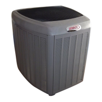
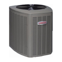
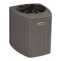
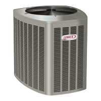
The XC17 is a high efficiency residential split−system air
conditioner unit, which features a one−stage scroll
compressor, icomfortt control and HFC−410A refrigerant.
Units are available in 2, 3, 4 and 5−ton sizes. This model
series is designed for use with an expansion valve
metering device only. Refer to the XC17 Engineering
Handbook for ordering the correct indoor coil expansion
valve.
This model is also SunSourcet ready beginning with
XC17−XXX−230−02 build.