Page 56
XC17
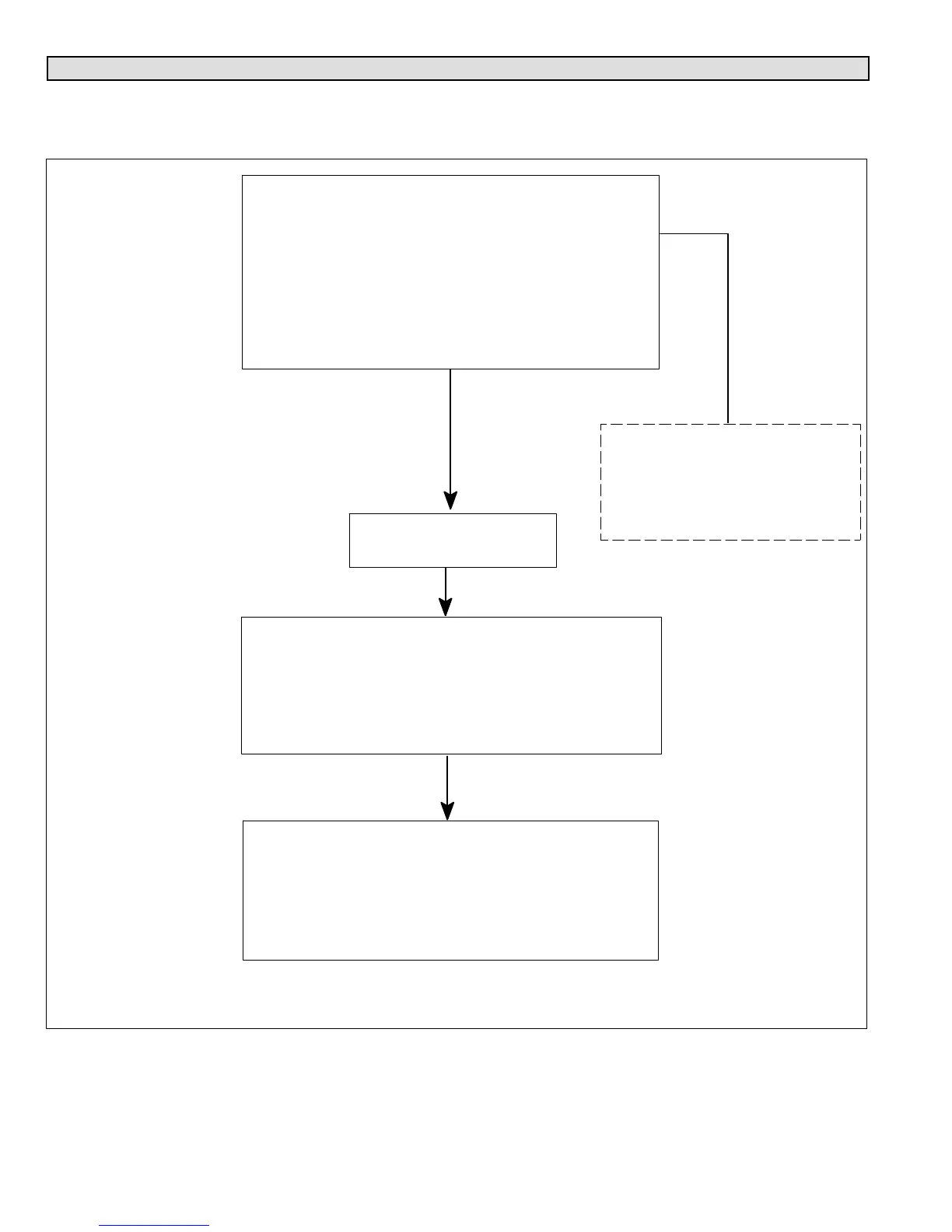
Unit Sequence of Operations
The following figures illustrated the overall unit sequence of operations along with various pressure switches and
temperature sensor operations. The figures also illustration the use of the compressor anti−short cycle function in relations
to unit Status, Fault and Lockout LED Codes system operations interaction.
On 24VAC power−up or air conditioner control (A175)
reset, the air conditioner control shall perform the
following tasks:
1. Start the anti−short cycle delay.
2. Check temperature sensor and pressure switches at
the start of cooling demand.
3. Air Conditioner control responds to the thermostat
input after the anti−short cycle timer expires. If there is
no thermostat input, control goes to standby mode.
Air conditioner control
receives cooling input.
The air conditioner control (A175) will apply:
1. 24VAC to compressor contactor output Y1 OUT..
2. Output between 24 and 32 VDC on air conditioner
control’s ECM fan terminals ECM Y1 FAN and ECM C.
NOTE − If low pressure switch is closed, system will ignore
for 90 seconds.
The outdoor fan control (A177) will:
Receive the DC voltage signal from the outdoor control
(A175) and converted the signal to a pulse width
modulation (PWM) signal. Jumper settings will determine
fan PWM OUT fan speed.
NOTE Refer to table 14 for jumper settings.
For low pressure (S87) and high
(S4) switches sequence of
operations, see figures 33 and 34.
For temperature switch RT28
sequence of operations, see figure
35.
Figure 32. One−Stage Cooling Unit Sequence of Operation

 Loading...