Page 32
XC17
System Operation
IMPORTANT
Some scroll compressor have internal vacuum protector
that will unload scrolls when suction pressure goes below
20 psig. A hissing sound will be heard when the
compressor is running unloaded. Protector will reset
when low pressure in system is raised above 40 psig. DO
NOT REPLACE COMPRESSOR.
The air conditioner control (A175) provides the following
system functions:
S Compressor anti−short−cycle delay.
S High and low pressure switches
S Ambient and Discharge Line Temperatures Monitoring
and Protection.
S Five strikes lockout safety feature for High/Low Pressure
Switches and High Discharge Line Temperature. See
figures 34, 33 and 35 feature function.
COMPRESSOR ANTI−SHORT CYCLE DELAY
The air conditioner control (A175) protects the compressor
from:
S Short cycling (five minutes) when there is initial power up
S Interruption in power to the unit
S High or low pressure switch or discharge line sensor trips
S Delay after Y1 demand is removed.
The anti−short timer in the air conditioner control is five (5)
minutes. To override timer when active or inactive − place
jumper on the field test pins between 1 and 2 seconds.
Resetting Anti−Short Cycle Delay
The FIELD TEST pins (E33) on the air conditioner control
(A175) can be jumpered between 1 to 2 seconds to bypass
delay.
HIGH AND LOW PRESSURE SWITCHES
The unit’s reset pressure switches LO PS (S4) and HI PS
(S87) are factory−wired into the air conditioner control
(A175) on the LO−PS and HI−PS terminals, there locations
are illustrated on page 5. Sequence of operations for both
pressure switches are provided in figures 34 and 33.
When replacing either the high or low pressure switches,
tighten switch using either of the following methods:
S With Torque Wrench: Finger tighten and torque to 100
inch pounds.
S Without Torque Wrench: Finger tighten and use an
appropriately sized wrench to turn an additional 1/2
to full turn clockwise.
1
2
3
4
5
6
7
8
9
10
11
12
1/2 TURN TO
FULL TURN
HIGH DISCHARGE LINE TEMPERATURE SENSOR
(RT28)
The high discharge line temperature sensor location is
illustrated on page 5. This sensor’s sequence of
operations is provided in figure 35.
High Discharge Line Sensor Open/Shorted Event
Condition
Discharge sensor open / short fault is ignored during initial
90−seconds of compressor run time. After that, if discharge
temperature sensor is detected open or short, the control
will de−energize all the outputs and anti−short cycle timer is
started. Discharge sensor faulty alert LED code will be
displayed.
OUTDOOR AMBIENT TEMPERATURE (RT13)
If the outdoor ambient temperature sensor detected a
open, or out of range −40ºF to +140ºF (−40ºC to 60ºC) then
LED alert codes are displayed, however cooling operation
will continue. See table 9 for LED alert codes for the
ambient sensor. Location of outdoor ambient temperature
sensor is illustrated on page 5.
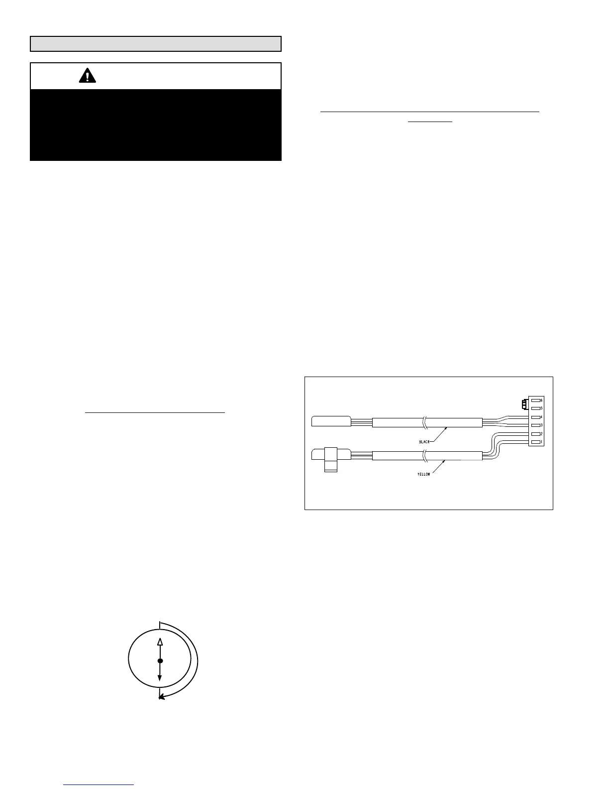
COIL TEMPERATURE SENSOR
This model does not use a coil temperature sensor. The
cable assembly attached to the air conditioner control
(A175)’s E30 connection has a 10K resister installed
between pins 5 and 6 as illustrated in figure 18. No alerts or
alarms would be generated if resistor is damage.
10K resistor
High Discharge Line
Temperature Sensor
Ambient Air
Temperature
Sensor
Figure 18. 10k Resistor Location
TESTING AMBIENT AND HIGH DISCHARGE LINE
TEMPERATURE SENSORS
Sensors connect through a field-replaceable harness
assembly that plugs directly into the air conditioner control
(A175). Through these sensors, the air conditioner control
can monitor outdoor ambient and discharge line
temperature fault conditions. As the detected temperature
changes, the resistance across the sensor changes.
figures 7 and 8 lists how the resistance varies as the
temperature changes for both type of sensors. Sensor
resistance values can be checked by ohming across pins
shown in table 6.
When a sensor indicates a resistance value that is not
within the range as listed in table 6, then the following
condition may be present:

 Loading...