58
XC20
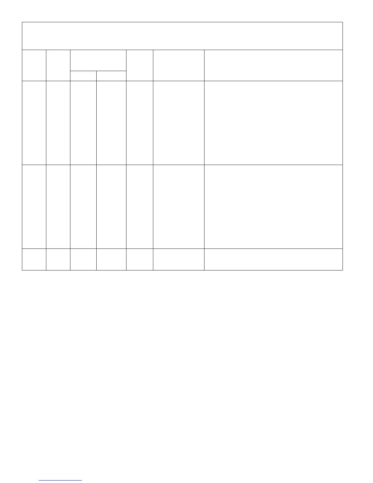
Table 11. Outdoor Control 7-Segment Display Alert Codes - Compressor
System fault and lockout codes take precedence over system status codes (cooling, heating operating percentages or defrost/dehumidification). Only
the latest active fault or lockout codes are displayed (if present). If no fault or lockout codes are active, then system status codes are displayed. Alert
codes are also displayed on the iComfort Wi-Fi
®
thermostat..
Alert
Codes
Inverter
Code
Inverter LED Flash
Code (number of
flashes)
Priority Alarm Description Possible Causes and Clearing Alarm
Red LED Green LED
E 440 13 1 flash 3 flashes Moderate
Heat sink temperat
ure is approaching
limit. The com
pressor speed auto
matically slows to
reduce heat sink
temperature. The
control sets indoor
CFM and outdoor
RPM to values ac
cording to demand
percentage rather
than the actual Hz.
Alarm is automatic
ally cleared.
Issue: Feedback from supplier tear down of inverter indicates
that the screws that hold the inverter to the inverter board were
loose causing poor contact between these two components.
Corrective action: Tighten screws that hold the heat sink to the
inverter control board.
NOTE: Wait 5 minutes to all capacitor to discharge before check
ing screws.
E 441 14 1 flash 4 flashes Moderate
Compressor slow
down due to high
compressor current.
Compressor current
is approaching limit.
The compressor
speed automatically
slows. The control
sets indoor CFM
and outdoor RPM to
values according to
demand percentage
rather than the actu
al Hz. Alarm is auto
matically cleared..
Issue: Possible issue is system running at high pressures.
Check for high pressure trips or other alert codes in room ther
mostat and outdoor control.
E 600 N/A N/A N/A Critical
Compressor has
been cycled OFF by
utility load-shedding
function.
Load-shedding function: Provides a method for a local utility
company to limit the maximum power level usage of the outdoor
unit. The feature is activated by applying 24 volts AC power to
the L and C terminals on the outdoor control.

 Loading...