33
XC20
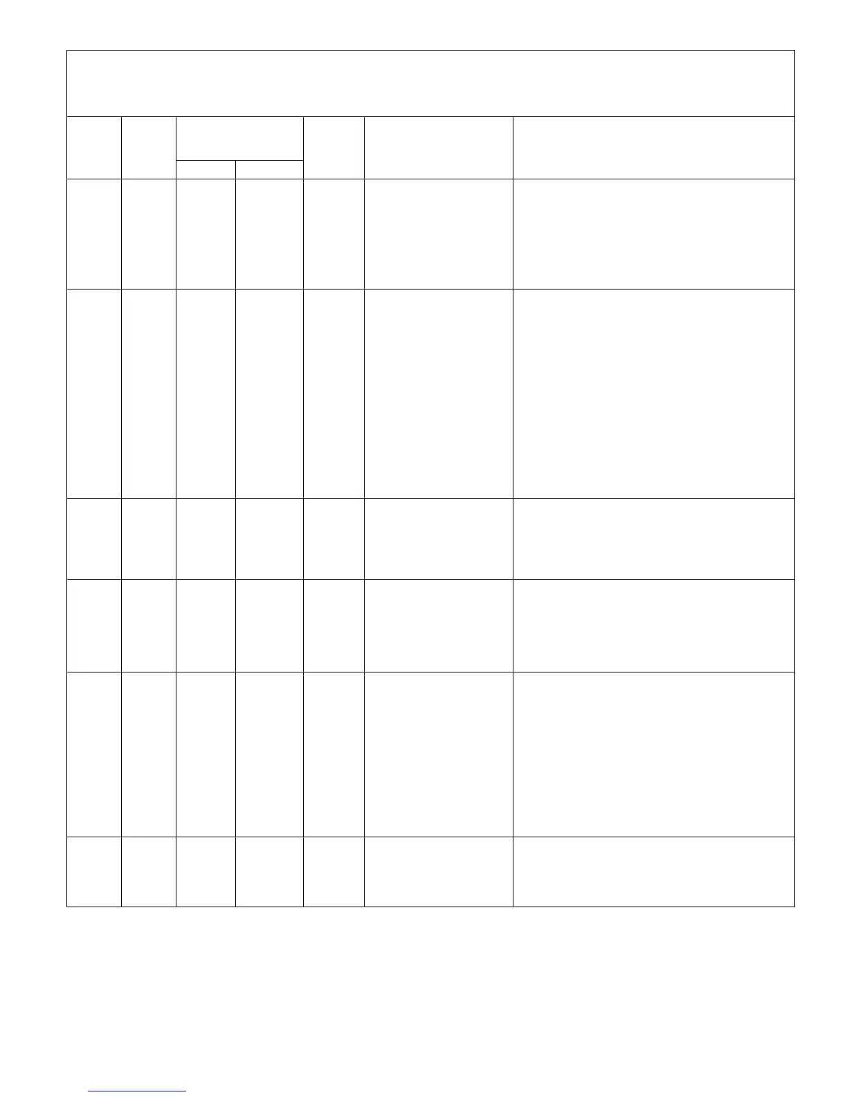
Table 6. Outdoor Control 7-Segment Display Alert Codes and Inverter LED Flash Codes
NOTE - System fault and lockout codes take precedence over system status codes (cooling, heating operating percentages or defrost/dehumidification).
Only the latest active fault or lockout codes are displayed (if present). If no fault or lockout codes are active, then system status codes are displayed. Alert
codes are also displayed on the iComfort Wi-Fi
®
thermostat.
Alert
Codes
Inverter
Code
Inverter LED Flash
Code (number of
flashes)
Priority Alarm Description Possible Causes and Clearing Alarm
Red LED Green LED
E 430 26 2 flashes 6 flashes
Moderate /
Critical
Compressor start failure.
If condition is detected, outdoor unit compressor and fan
stop. Antishort cycle is initiated. If condition occurs 10
times within an hour, system is locked out.
Indicates poor connection at compressor harness, im
proper winding resistance, locked compressor rotor, or
flooded compressor.
To clear, disconnect power to outdoor unit and restart.
E 431 27 2 flashes 7 flashes
Moderate /
Critical
Error occurs when PFC de
tects an over-current condi
tion of 100A, the control will
display a moderate code. If
condition is detected, out
door unit will stop (Com
pressor and fan). Anti-short
cycle is initiated. Inverter is
unavailable to communicate
with the outdoor control for 3
minutes. If condition occurs
10 times within a 60 minute
rolling time period, system
will lock out and display a crit
ical code.
Issues:
(1) Indicates power interruption, brownout, poor electrical
connection or loose inverter input wire.
(2) System testing was set up and code was generated
when the reversing valve is de-energized coming out of
defrost (code appears with or without 30 compressor
delay).
Corrective Actions:
(1) Check for proper main power to outdoor unit and for
any loose electrical connections.
(2) Outdoor control boards with part # 103686-03 have
software update to delay the de-energizing of the revers
ing valve by four seconds when coming out of defrost.
E 432 28 2 flashes 8 flashes
Moderate
/ Critical
The inverter has detected a
DC link high voltage condi
tion.
Error occurs when the DC link capacitor voltage is greater
than 480VDC. If condition is detected, outdoor unit com
pressor and fan stop. Antishort cycle is initiated. If condi
tion occurs 10 times within an hour, system is locked out.
System stops. To clear, disconnect power to outdoor unit
and restart.
E 433 29 2 flashes 9 flashes
Moderate
/ Critical
The inverter has detected a
compressor over-current
condition
.
Error occurs when compressor peak phase current is
greater than 28A. Inverter issues code 14 first and slows
down to try to reduce the current. If the current remains
high, outdoor unit compressor and fan stop. Antishort
cycle is initiated. If condition occurs five times within an
hour, system is locked out. To clear disconnect power to
outdoor unit and restart.
E 434 53 5 flashes 3 flashes
Moderate /
Critical
Outdoor control has lost
communications with the
inverter for greater than 3
minutes. Outdoor control
will stop all compressor de
mands, recycle power to
the inverter by de-energiz
ing the contactor for 2
minutes. If this occurs 3
time in one thermostat call,
the outdoor unit will locked
out and display a critical
code.
Issues:
(1) Loose electrical connections.
(2) Interruption of main power to inverter.
Corrective Actions:
(1) Check all electrical connections.
(2) Check for proper main power to inverter.
E 435 60 6 flashes OFF
Moderate /
Critical
Inverter internal error.
When this error occurs, the outdoor control cycles power
to the inverter by opening the contactor for two minutes.
Check that the EEPROM is properly seated. After power
is cycled to the inverter 3 times, the outdoor unit is locked
out
.

 Loading...