27
XC20
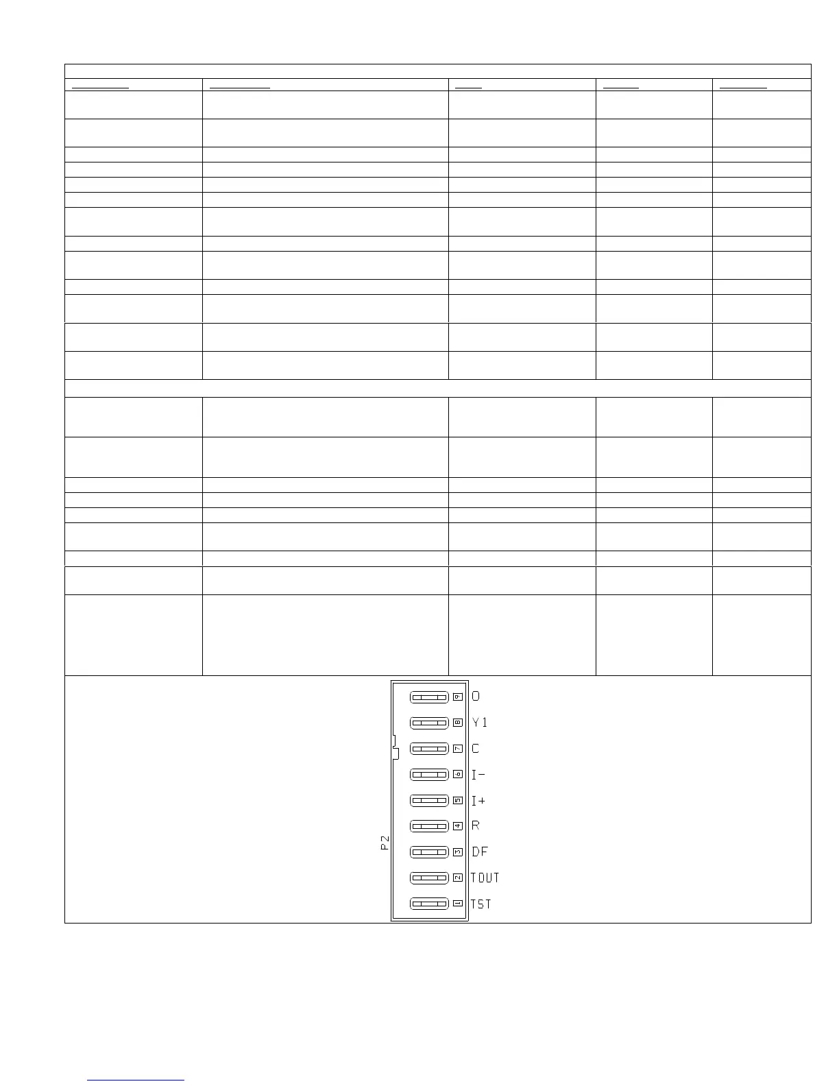
TABLE 5
Outdoor Control Terminal Designations and Input /Outputs (see figure 14 for terminal locations)
Designator Description Input Output Common
O
Unused on XC20, for heat pump applications
only.
N/A
Switched 24VAC
nominal
N/A
O OUT
Unused on XC20, for heat pump applications
only.
N/A N/A 24VAC common
LO PS Low pressure switch N/A 5ma @18VAC N/A
LO PS Low pressure switch sensing connection 5ma @18VAC N/A N/A
Hi PS High pressure switch N/A 24VAC nominal N/A
Hi PS High pressure switch sensing connection 24VAC nominal N/A N/A
TP
Top cap thermostat switch (in series with the HI
PS)
N/A 24VAC nominal N/A
TP Top cap thermostat switch sensing connection 24VAC nominal N/A N/A
Cntctr
Control (inverter power) contactor switched out
put (in series with the HI PS and TC)
N/A
Switched 24VAC
Nominal
N/A
Cntctr Contactor common N/A 24VAC common
Fan PWM PWM fan output N/A
1097% duty cycle,
1923 VDC peak
N/A
COM PWM fan common connection N/A N/A
Fan PWM com
mon
Fan Park
PWM fan parking spot for unused terminal, not
connected.
N/A N/A N/A
P2 Terminal Designations
O
Unused on XC20, for heat pump applications
only.
24VAC nominal from ther
mostat and loaded to draw
17ma at 30VAC
N/A N/A
Y1 Y1 emergency input
24VAC nominal from ther
mostat and loaded to draw
17ma at 30VAC
N/A N/A
C 24VAC nominal power return. N/A N/A 24VAC common
i Low data line. Data Data N/A
i+ High data line. Data Data N/A
R 24VAC nominal power input.
24VAC nominal board main
power input.
N/A N/A
DF OEM test N/A N/A N/A
TOUT
26Vdc transistor output to Lennox factory OEM
tester
N/A N/A N/A
TST
OEM test pin.
In each terminal box:
P2 Terminal 1 TEST
P2 Terminal 2 TOUT
P2 Terminal 3 DF
P2 Terminal 4 R
24VAC nominal 17ma @
30VAC
N/A N/A

 Loading...