14
XC20
COOLING SYSTEM (HFC410A)
D Total equivalent length equals 180 feet (all piping and
fittings included).
NOTE - This is a general guide. Lengths may be more or
less, depending on remaining system design factors.
D Maximum linear (actual) length = 150 feet.
D Maximum linear liquid lift = 60 feet.
NOTE - Maximum lifts are dependent on total length, num
ber of elbows, and other factors that contribute to total
pressure drop.
D Maximum linear length of vapor riser = 60 feet.
D Size vertical vapor riser per table 2.
D Line set lengths up to 50 linear feet: Use rated line
sizes listed in table 2.
D Line set lengths between 51 and 150 linear feet:
Crankcase heater and nonbleed port TXV factory-in
stalled. No additional components required. Vertical
vapor riser must be sized to the vapor riser listed in
table 3 on systems with line sets longer than 51 feet.
Use tables 3 and 4 to determine the correct liquid and
vapor line sizes.
D Line set lengths over 150 linear feet: Not recom
mended.
D Additional oil is not required for systems with line
lengths up to 150 feet.
NOTE - Recommended POE oils are Mobil EAL ARCTIC
22 CC or ICI EMKARATEt RL32CF.
SUCTION TRAPS
In systems with the outdoor unit 5 to 60 feet above the in
door unit, one trap must be installed at the bottom of the
suction riser.
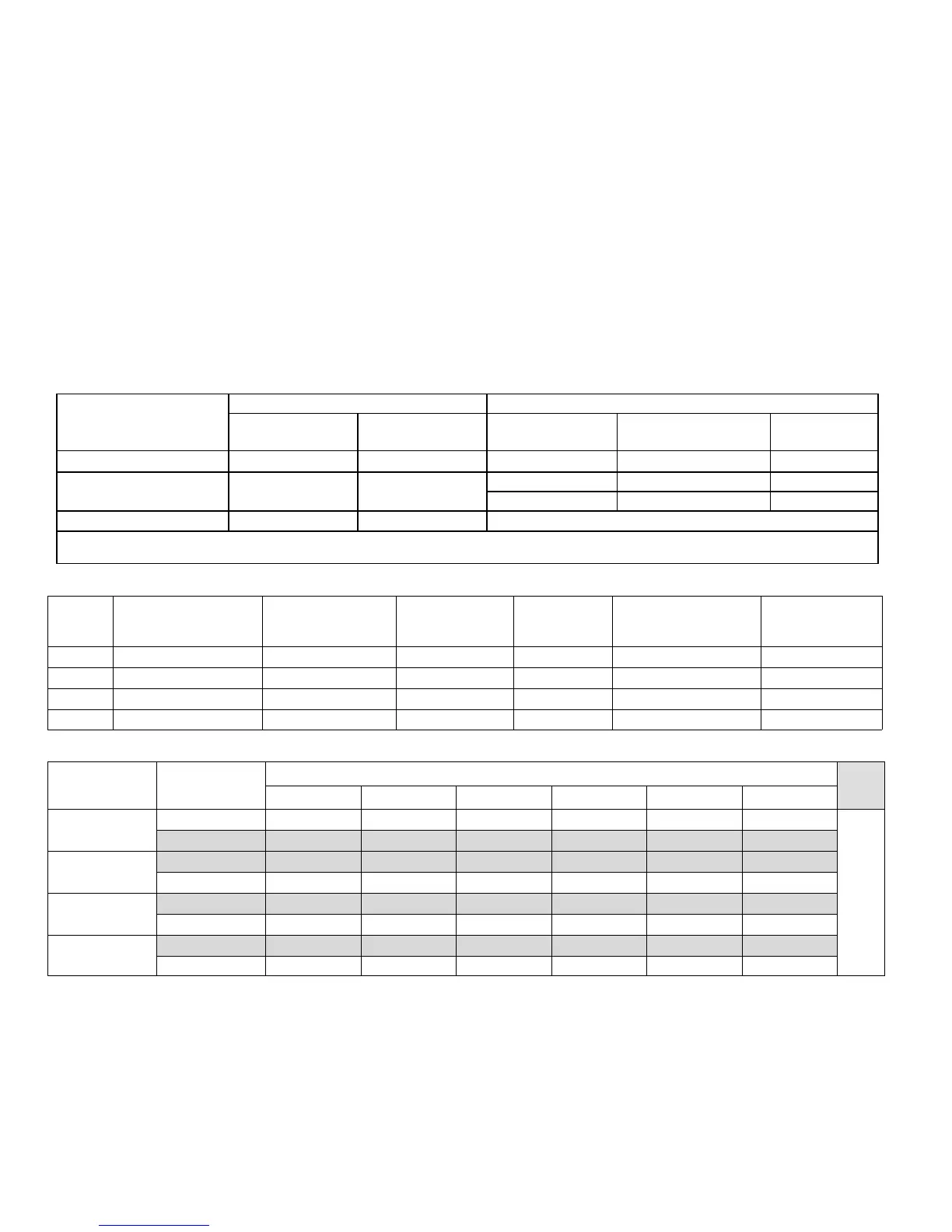
Table 2. Standard Refrigerant Line Set — Up to 50 Linear Feet
Model Number (-xx*)
Valve Size Connections Recommended Line Sets
Liquid Line Suction Line
L15 Line Set
Model
Line Set Length
Catalog
Number
XC20-024-230-XX 3/8” (10 mm) 3/4” (19 mm) L15-41-30 30 feet (9.1 m) 89J60
XC20-036-230-XX
XC20-048-230-XX
3/8” (10 mm) 7/8” (22 mm)
L15-65-40 40 feet (12.2 m) 89J61
L15-65-50 50 feet (15.2 m) 89J62
XC20-060-230-XX 3/8” (10 mm) 1-1/8” (29 mm) ** Field-fabricated
* Applicable to all minor revision numbers unless otherwise specified.
** Some applications may require a field-provided 1-1/8” to 7/8” adapter.
Table 3. XC20 Line Set Guidelines — 51 to 150 Linear Feet in Length
Model
Maximum Total
Equivalent Length (ft)
Maximum Linear
(actual) Length (ft)
Maximum Vapor
Riser (ft)
Maximum
Linear Liquid
Lift (ft)
Preferred Vapor Line
Sizes for Horizontal
Runs
Required Vapor
Riser Size
024 180 150 60 60 3/4” 5/8”
036 180 150 60 60 7/8” 3/4”
048 180 150 60 60 7/8” 7/8”
060 180 150 60 60 7/8” 7/8”
Table 4. Liquid Line Diameter Selection Table
Unit
Line Size
Total Linear Length (feet)
25 50 75 100 125 150
024
5/16” 25 50 55 48 40 33
Max. Elevation
(ft)
3/8” 25 50 60 60 60 60
036
3/8” 25 50 60 56 51 45
1/2” 25 50 60 60 60 60
048
3/8” 25 50 50 41 31 22
1/2” 25 50 60 60 60 60
060
3/8” 25 50 36 22 8 NR
1/2”
25
50 60 60 60 59
Note Shaded rows indicate rated liquid line size.
1. Find your unit on the left side of the table.
2. Start with the rated liquid line size (shaded row) for the outdoor unit.
3. Select the actual total linear length of your system shown at the top of the table.
4. The elevation listed in the table is the maximum allowed for the liquid line listed.
5. Consider the larger liquid line size shown in the table if the elevation does not meet your requirements.

 Loading...