• 6 •
RECOMMENDATIONS FOR INSTALLATION
FAN COIL INSTALLATION
Before installing the appliance, ensure that:
1) the place of installation has sufcient space for carrying out installation as
well as routine and extraordinary maintenance work (see Pic. 4).
2) There are no obstructions for air intake and delivery.
3) The water connections are of the sizes, in the position and spaced apart as
required by the appliance (see Dimension).
4) The system pressure does not exceed 8 bar for the water versions.
5) The electricity supply corresponds to the data on the appliance rating plate
and that there is a afety switch readily accessible to the user to cut off the power
supply whenever necessary.
6) The safety switch is in the OFF position so that there is no voltage on the
appliance supply line.
Before installing the appliance, remove the housing (if present). Raise the aps
covering the control panel and the water connections. Remove the two screws
xing the housing to the fan coil load-bearing structure. Gipping the rear of the
housing, remove it as shown in the Pic. 5 (NOTE: be careful of the lugs on the
front part of the load-bearing structure, as shown in Pic.10).
Put the cabinet in the packing box to prevent it from being soiled or damaged
(Pic.6)
Offer the appliance up to the required point of installation and mark, through the
xing holes, the points on the wall where the holes should be driller for the 4
screw anchors, as shown in Pic. 7.
Pic. 04
Pic. 06Pic. 05
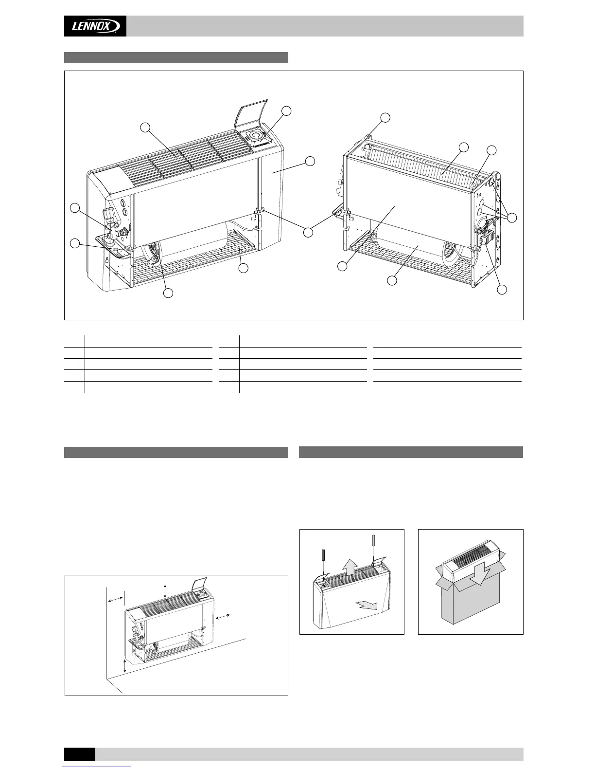
MAIN COMPONENTS
Pic. 03
1 Heat exchanger
2 Water low temperature sensor
3 Control panel
4 Drain pan
5 Air lter
6 Electric motor
7 Centrifugal fan
8 Condense discharge
9 Knockouts
10 Valves
11 Auxiliary drain pan
12 Cabinet
13 Bearing structure
14 Terminal board
15 Supply grills
3
4
7
8
9
2
6
5
12
14
10
11
13
15
1
1
5
0
m
m
1
5
0
m
m
150 mm
130 mm
 Loading...