507581-04Page 34 of 60 Issue 2128
Condensate Piping
This unit is designed for either right or left side exit of
condensate piping in upow applications. In horizontal
applications, the condensate trap must extend below the
unit. An 8” service clearance is required for the condensate
trap. Refer to Figure 52 and Figure 53 for condensate trap
locations. Figure 59 shows trap assembly using 1/2” PVC
or 3/4” PVC.
NOTE: If necessary, the condensate trap may be installed
up to 5’ away from the furnace. Use PVC pipe to connect
trap to furnace condensate outlet. Piping from furnace
must slope down a minimum of 1/4” per ft. toward trap.
1. Determine which side condensate piping will exit the
unit, location of trap, eld-provided ttings and length
of PVC pipe required to reach available drain.
2. Use a large at head screw driver or a 1/2” drive
socket extension and remove plug (Figure 52) from
the cold end header box at the appropriate location
on the side of the unit. Install provided 3/4 NPT street
elbow tting into cold end header box. Use Teon tape
or appropriate pipe dope.
3. Install the cap over the clean out opening at the base
of the trap. Secure with clamp. See Figure 59.
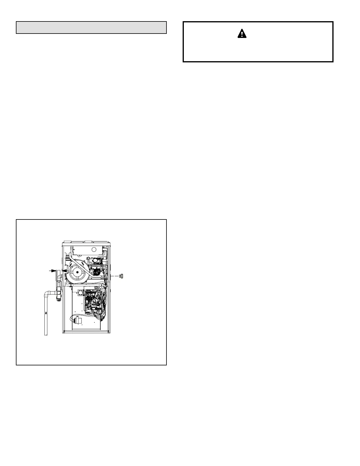
Figure 52. Condensate Trap and Plug Locations
(Unit shown in upow position)
CONDENSATE TRAP AND PLUG LOCATIONS
(Unit shown in upflow position)
Plug
(same on
left side)
Trap
(same on
right side)
1-1/2 in.
NOTE - In upflow applications where side return air
filter is installed on same side as the condensate
trap, filter rack must be installed beyond condensate
trap or trap must be relocated to avoid interference.
4. Install drain trap using appropriate PVC ttings, glue
all joints. Glue the provided drain trap as shown in
Figure 59. Route the condensate line to an open drain.
Condensate line must maintain a 1/4” downward slope
from the furnace to the drain.
Do not use copper tubing or existing copper condensate
lines for drain line.
CAUTION
5. Figure 54 and Figure 55 show the furnace and
evaporator coil using a separate drain. If necessary
the condensate line from the furnace and evaporator
coil can drain together. See Figure 57 and Figure 58.
Upow furnace (Figure 53) - In upow furnace
applications the eld provided vent must be a minimum
1” to a maximum 2” length above the condensate drain
outlet connection. Any length above 2” may result in a
ooded heat exchanger if the combined primary drain
line were to become restricted.
Horizontal furnace (Figure 55) - In horizontal furnace
applications the eld provided vent must be minimum
4” to a maximum 5” length above the condensate drain
outlet connection. Any length above 5” may result in a
ooded heat exchanger if the combined primary drain
line were to become restricted.
NOTE: In horizontal applications it is recommended to
install a secondary drain pan underneath the unit and
trap assembly.
NOTE: Vinyl tubing may be used for condensate drain.
Tubing must be 1-1/4” o.d. X 1” i.d. and should be
attached to the drain on the trap using a hose clamp.
6. If unit will be started immediately upon completion of
installation, prime trap per procedure outlined in Unit
Start-Up section.
Condensate line must slope downward away from the
trap to drain. If drain level is above condensate trap,
condensate pump must be used. Condensate drain line
should be routed within the conditioned space to avoid
freezing of condensate and blockage of drain line. If
this is not possible, a heat cable kit may be used on the
condensate trap and line. Heating cable kit is available in
various lengths; 6 ft. (1.8 m) - kit no. 26K68; 24 ft. (7.3 m) -
kit no. 26K69; and 50 ft. (15.2 m) - kit no. 26K70.
 Loading...