• 23 •
2%
AQUALEAN - AWC/AWH - MIL118E-1407 / 10-2013
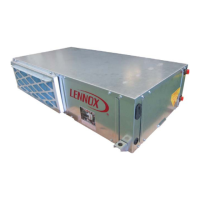
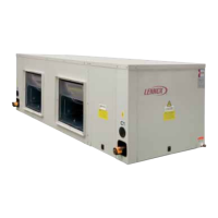
INSTALLATION
2.2.- UNIT INSTALLATION
Units must be installed by qualifi ed technicians. Any modifi cations done on the units will be made under customer´s
responsibility, and Lennox conformity declaration certifi cate will not be valid.
Hidraulic circuit:
• Make sure that water connections are correct, water inlet (down side), water outlet (upper side).
Lennox offers this element as an option.
• Install cut off valves at inlet and outlet water connections, because of in case of repairs, the hydraulic circuit can be
independent.
• Install water inlet and water outlet connections with a differential gauge device in order to see the pressure difference
between
the outlet an inlet connections.
• At the end Install an adequate water pump, and all the necessary elements for the installation
ake sure to disconnect power suppl
Water fi lter in the inlet water connection has to be used. The ste
of the mesh should be less
than
1.5 mm which avoids welded and dirt
se fl exible components for the h
draulic connection between the unit and the installation in
order to
revent the transmission of vibrations
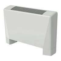
AIR FLOW:
Airfl ow can be adjusted though the unit remote display between maximum/nominal/minimum
With “AUTO” the controller regulates the airfl ow between maximun and minimum values to assure the correct unit
operation mode.
DRAINAGE TUBE
• Use the fl exible tube connected to the drip tray as a drainage tube. Cause a siphon with this tube in order to avoid
the inlet of scents from the installation to the unit.
Install a siphon from the drainage tube of the drip tray with a difference in height of 80 mm to prevent from not evacua-
ting due to the negative pressure created by the fans. The pipe will slope down 2% to make it easier for the conden-
sates to drain off.
Inspection and
cleaning stopper.
Min. 80mm
 Loading...