IOM / ROOFTOP BALTIC Series - 0704-E Page 55
VENTILaTION : AIRFLOW BALANCING
EXAMPLE
The unit used for this example is a BGK035ND1M with Economiser and Electric Heater type H
It is fitted with a fan which curve is shown on page 57 and a 2.2kW motor.
- Motor rpm: 1430 rpm
- cos ϕ = 0.81
- Voltage = 400V
- Current = 3.77A (measured)
P
mech fan
= V x I x
√√
√√
√ 3 x cos
ϕ ϕ
ϕ ϕ
ϕ x
ηη
ηη
η
mech motor
x
ηη
ηη
η
Transmission
= 400 x 3.77 x 3 x 0.81 x 0.76 x 0.9 = 1.45kW
The unit is also fitted with a transmission kit 7
- Fixed Fan pulley : 160mm
- Motor adjustable pulley type "8450" opened 4 turns from fully closed or measured distance between pulley end plates is
26.4mm: from table 1 it can be determined that the motor pulley has a diameter of 99.2mm
rpm
FAN
= rpm
MOTOR
x D
M
/ D
F
= 1430 x 99.2 / 160 = 886 rpm
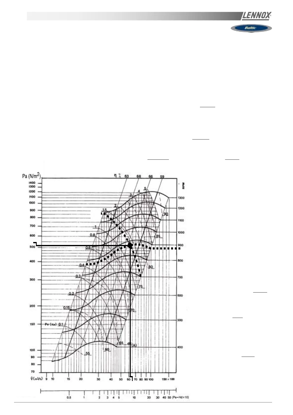
Using the fan curve below the operating point can be located.
It can be determined that the fan is providing approximately
6300 m3/h with a total pressure P
TOT
= 530 Pa
886
530
63
1,45
Hd (mmH2O)
The pressure losses in the unit are
the sum of all pressure drops across
the different parts of a unit :
- Coil and filter (measured) = 104 Pa
- Inlet into the unit = 30 Pa
- Options = 23 Pa for economiser and
91 Pa for electric heater H
∆P = 104 + 30 + 23 + 91 =
248 Pa
The dynamic pressure at 6300m3/h is
given at the bottom of the fan curve P 57
Pd =
81Pa
The external static pressure available
is therefore
ESP = P
TOT
- Pd - ∆PI
NT
= 530 - 81 - 248 = 201 Pa
Fig. 36
 Loading...