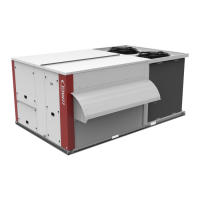
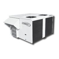
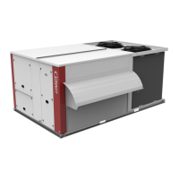
Do you have a question about the Lennox Baltic BHK 070 and is the answer not in the manual?
Guidance on safe transportation and handling procedures for the unit.
Specifies the necessary clearances around the unit for operation and maintenance.
Procedures for installing the unit on various types of roof mounting frames.
Guidance on installing roof curbs and flashing for weatherproofing.
Steps to take before connecting the unit to the power supply.
Step-by-step guide for starting the unit after installation.
Using the DC50 display for basic unit monitoring and control.
Navigating the DS50 display for service and advanced diagnostics.
List and descriptions of error codes generated by the Climatic 50 controller.
Details on connecting and operating Climalink and Climalook systems.
Troubleshooting steps for problems entering access codes or interrupted communication.
Wiring diagram for the main power circuit of the unit.
Wiring diagram for the Climatic 50 controller unit.
Diagrams showing input connections for the Climatic 50 controller.
Diagrams illustrating output connections for the Climatic 50 controller.
Wiring diagram for the DAD smoke detector system.
Wiring diagram for the TCB (Terminal Connection Board).
Wiring diagram for the ADC (Advanced Control Pack).
Wiring diagrams for gas burner modules of various capacities.
Wiring diagrams for fully modulating and staged electric heaters.
Overall connection diagram for customer interfaces.
| Brand | Lennox |
|---|---|
| Model | Baltic BHK 070 |
| Category | Air Conditioner |
| Language | English |


